1 OVERVIEW
The Flagship FC7300 series is a high performance automotive grade hyper-converged processor (HPU) based on the multi-core Arm® Cortex-M7, which meets the requirements of ISO 26262 ASIL-D, the highest level of functional safety. To achieve this stringent safety goal, the FC7300 chips integrate several key safety mechanisms inside the chip, of which EIM (Error Injection Module) and ERM (Error Reporting Module) play a crucial role.
l EIM:The main purpose is to perform power-up and periodic self-test of ECC function by simulating ECC fault injection.
l ERM: It is mainly used to respond to ECC faults and trigger interrupts for troubleshooting to prevent the faults from causing the system functions to fail.
Working closely together, these two modules are the core hardware foundation for the FC7300 to achieve ASIL-D certification and ensure the reliable operation of safety-critical applications such as automotive power, chassis, and domain control.
2 Introduction to the ECC mechanism
There are two failure modes for memory
1. Illegal access, which is usually protected by memory management using MPUs.
2. Memory corruption, which is usually diagnosed by ECC, the mechanism of which can be implemented by software or hardware.
ECC is a common mechanism used by chips to secure information, mainly to avoid situations where data stored in storage devices is tampered with due to hardware interference.
2.1 ECC Basic Concepts
ECC full name Error Checking and Correcting, belongs to an error checking and correcting algorithm. In digital circuits, the smallest unit of data is called “bit (bit)”, also called data ‘bit’, “bit” is also the smallest unit of memory, which is signaled by the “1” and “0” indicate the data high and low level signals. Wireless electromagnetic interference and circuit noise in the space can cause bit flipping (“0” to “1”, ‘1’ to “0”) when the memory interacts with the CPU. "Typical ECC algorithms can correct single-bit errors and check for 2-bit errors.
2.2 Composition of ECC Data
The number of bit bits required for ECC is determined by the number of bits in the data segment. 8-bit data requires 5 ECC bits for checksum, and for every doubling of the data bits, ECC increases by only one checksum bit. For example, the number of ECC parity bits for 32-bit data is 7 bits.
2.3 Latent Failure Problems from ECC
Latent faults are a common problem faced by ECC mechanisms, where corruption of read data may not be detected for a number of reasons when checking for redundant parity bits. When the hardware is unable to solve the problem brought about by itself, software is required to assist in covering the corresponding faults.
Taking the FC7300 chip as an example, the chip provides the EIM peripheral, which is specialized in providing the function of flipping the data bits through the bus, it inserts the error injection channel of the module in the read path between the memory and the EDC/ECC function to achieve the means of injecting ECC faults. The software can actively inject ECC faults at power-up and then check that the ECC monitoring mechanism is functioning correctly, thus reducing the latent fault rate.
3 EIM与ERM模块的应用Application of EIM and ERM modules
3.1 Startup Detection
Verification for the ECC monitoring function is usually performed during the power-up process, using the EIM module to inject ECC faults into specific areas (e.g., SRAM, FLASH, TCM, etc.), then actively reading the fault address to trigger an ECC fault, and finally observing whether or not the fault can be responded to by the ERM module (e.g., whether or not an interrupt is triggered, whether or not the fault address is logged, etc.).
3.2 Runtime Moniting
After the power-on self-test has passed, the ECC monitoring function of the ERM is usually considered to be operational, and the corresponding monitoring function of the ERM will then be turned on, and interrupt response will be turned on for ECC troubleshooting (e.g., active attempts to clear faults, record DTC information, trigger reset, and other actions).
3.3 Shutdown Detection
The process of power-down detection is similar to power-up detection, but it should be noted that since the ECU will go into hibernation or directly power down after the power-down detection is completed, the detection results will not be saved through the RAM area. Therefore, the additional step after the power-down test is to retain the test results in the form of FLASH storage, read the result information at the next power-up, and confirm whether the fault area still exists.
3.4 Precautions
During the self-test process, an ECC fault is injected into the target area, which causes anomalies in the data in this area. The impact scenarios are as follows:
lIf the data shared by multiple cores is in the fault injection target area, core 1 will trigger an exception due to reading this shared data while core 0 is doing self-test. Since core 1 is not doing self-test but executing the program normally, core 1 will think that there is an ECC fault on the current chip and hang.
lIf the stack data is stored in the target area of the fault injection, a function call after the fault is injected will result in an exception triggered by reading or writing to the stack, and due to the faulty stack data, this will also result in an exception transfer error, which will result in the program running away.
lIf the interrupt vector table is stored in the fault injection target area, if an interrupt (e.g., timing interrupt, CAN interrupt, etc.) is triggered after the fault is injected, an exception in the vector table data will result in an abnormal final interrupt jump, and the program will fly.
Therefore, when using EIM for fault injection testing, care should be taken to consider all aspects of fault injection. For example, the variables shared by multiple cores should be prevented from being affected by the ECC fault injection; if the stack is placed in the TCM area, the stack switching work should be added when performing TCM related tests; when doing the FLASH self-test, in order to avoid code data anomalies, the code should be considered to be placed in the RAM for execution.
4 Introduction to ZC MuNiu
Based on the latest ARTOP architecture and the basic platform provided by the latest AUTOSAR R21-11 standard, the MNU Configuration Tool realizes the whole process of ECU configuration from configuration, validation to code generation according to the ECU configuration steps defined in the AUTOSAR development methodology. The main advantages can be summarized in the following aspects: the realization of the whole process of configuration, verification and code generation has completely realized the development requirements of the ECU configuration stage in the AUTOSAR development method.
The EimErmTst module is implemented in the ZC MuNiu SafetyLibrary software, which utilizes the Eim and Erm peripherals to achieve the power-on self-test function. The following will briefly describe the process of configuring the EimErmTst module using ZC MuNiu:
4.1 Introduction to EimErmTst Configuration
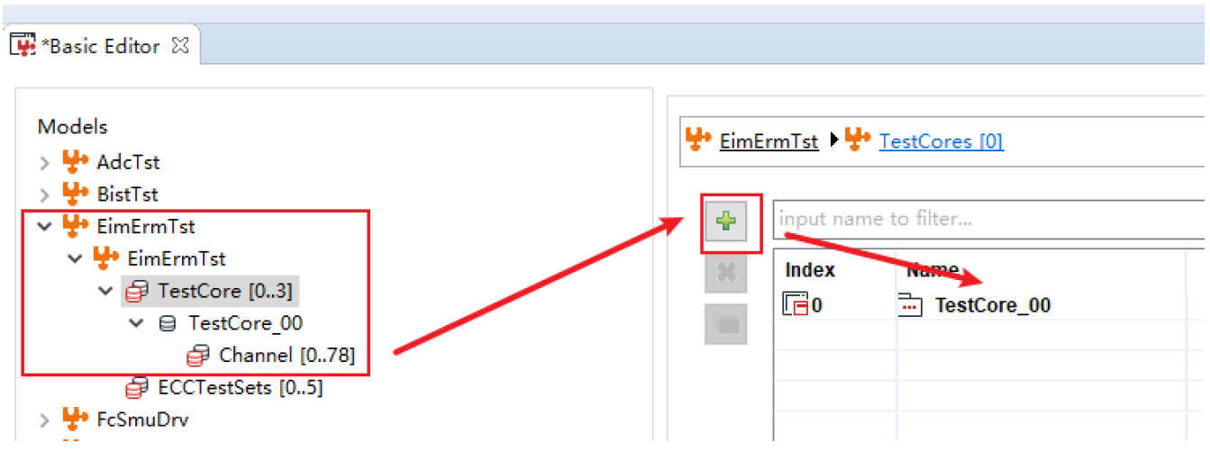
4.1.1 Adding Test Set
Test collections can be added for specific CPU cores through the TestCore interface.
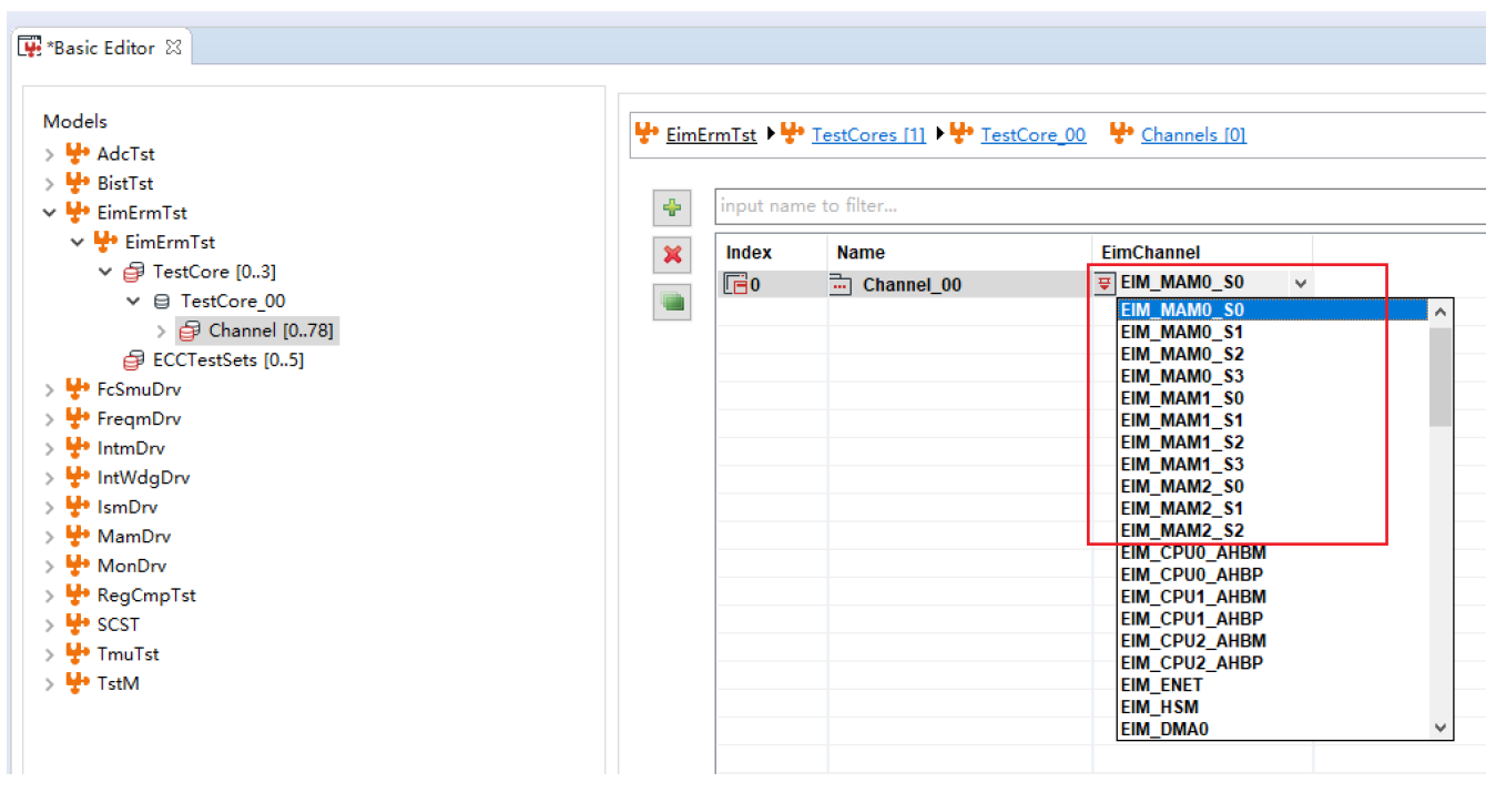
4.1.2 Configuring the EIM Test Channel
Multiple EIM test channels can be added under the corresponding Channel configuration page.
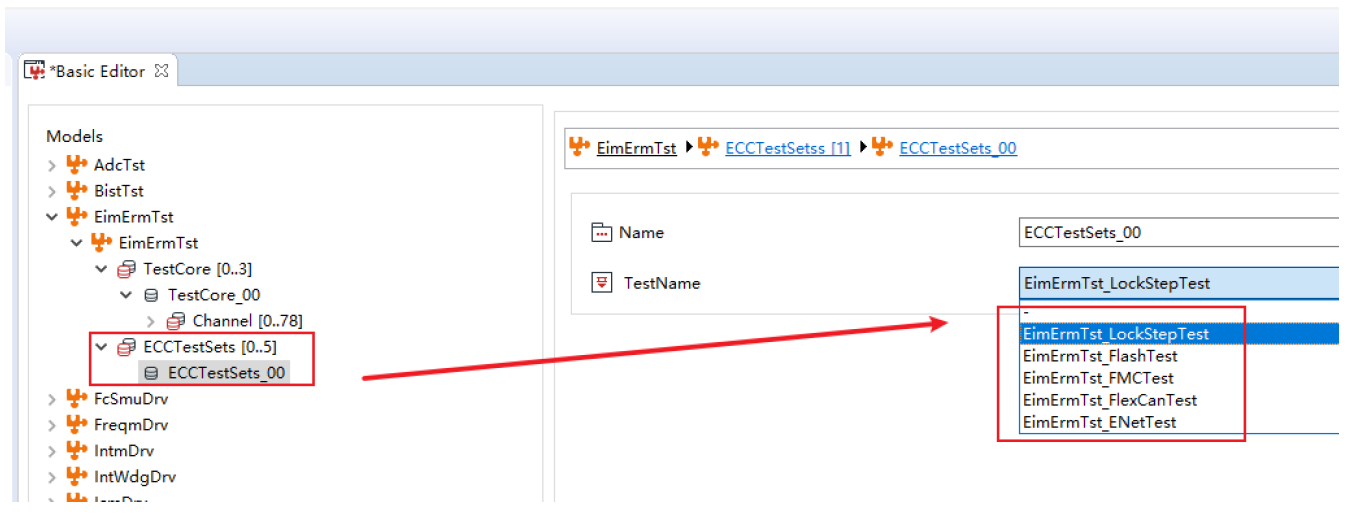
4.1.3 Configuration of Additional Security Mechanism Detection Functions
ZC MuNiu SafetyLibrary software is highly scalable. In response to the needs of customers for additional safety mechanisms, ZC can create targeted testing functions and provide the corresponding configuration items. In the ECCTestSets page, select the tests that need to be performed.
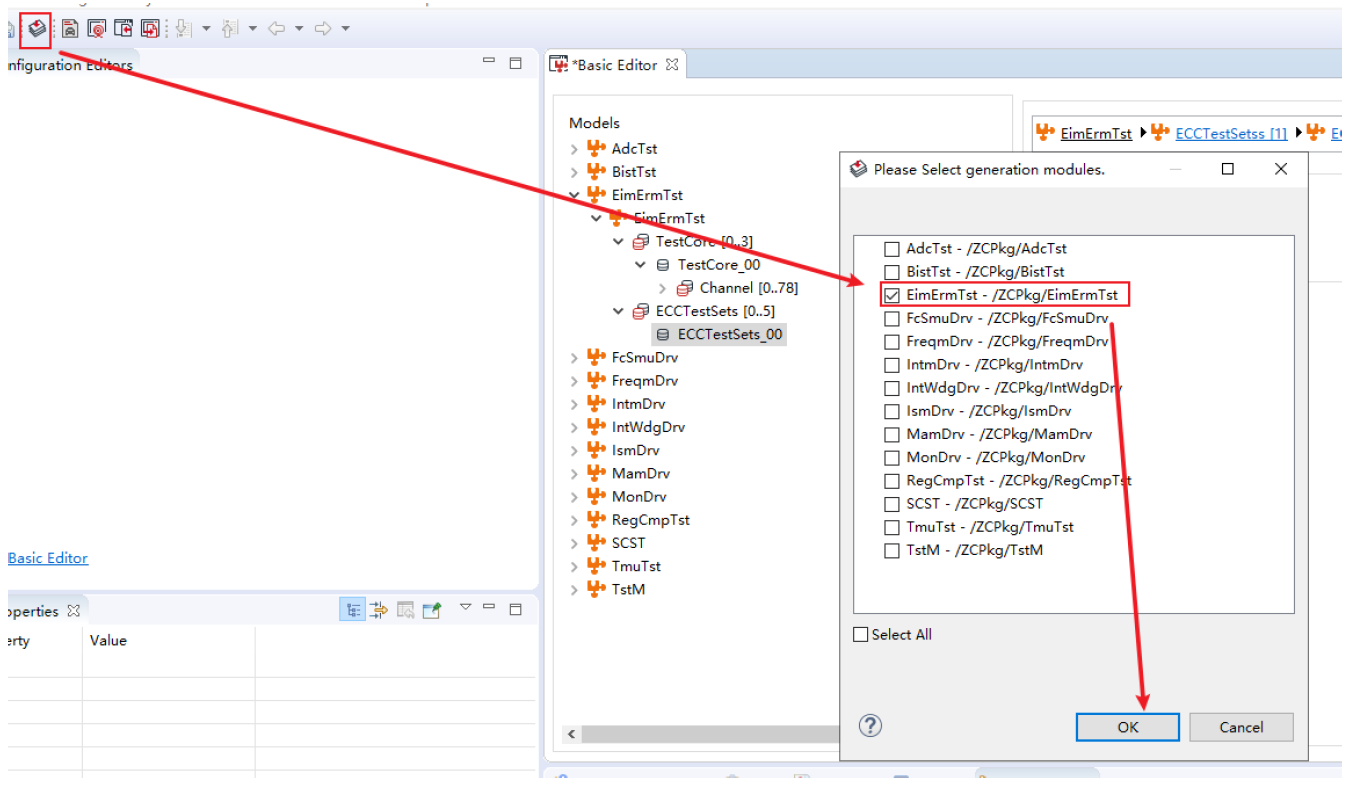
4.1.4 Generating Configuration Code
The EimErmTst related configuration code can be generated after all the functions are configured.
4.2 Areas of application
The ZC MuNiu configuration tool provides a user-friendly HMI for ECU controller software development. It supports the configuration of standard AUTOSAR basic software code modules as well as the development of configuration interfaces for complex drivers. Currently, it is mainly used in the following scenarios:
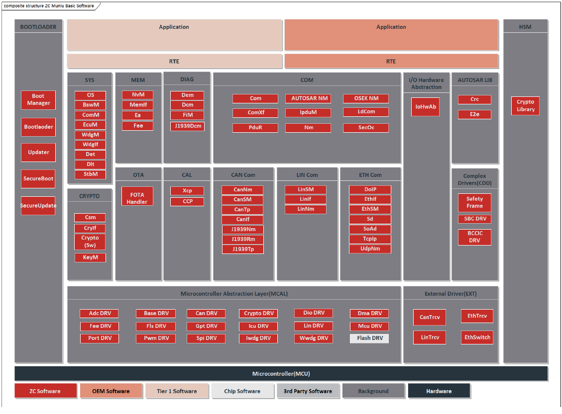
Ø ZC MuNiu Basic Software Platform Standard AUTOSAR Module Configuration
Ø ZC MuNiu Basic Software Platform Complex Driver Module Configuration
u SAFETY FRAME
u CRYPTO LIBRARY
u BCCIC
u SBC
Ø Collaboration with chip companies to provide configuration tools for MCU MCALs