未解决
已解决
ZC.QingLong AB SWAP Pragramming Based on Infineon TC3xx.
发布者:admin 发布于 2025-05-13 20:28:36
.
In the process of automotive intelligence development, although the importance and proportion of software continue to increase, the research and development cycle of the whole vehicle is invisibly shortened, so the risk of car recalls caused by software vulnerabilities continues to rise. At present, the total code amount of high-end cars has exceeded 100 million lines. Even if controlled according to the highest software standard of CMMI (Capability Maturity Model Integration) level 5, the code defect rate is still 0.32‰, and the scale of potential problems is not to be underestimated. Recall events require car manufacturers to pay huge direct and indirect costs.
For industries in development, facing the major trend of the development of smart cars, system update functions similar to those of Tesla will inevitably become the premise and foundation for the sustainable development of the industry. FOTA (Firmware Over-The-Air) has thus become one of the best solutions for addressing software vulnerabilities and upgrading smart car components.
FOTA wireless upgrades refer to providing firmware upgrade services for terminal devices with networking capabilities through the cloud. Users use the network to obtain smart terminal system upgrade packages on demand and in an easy-to-expand manner, and upgrade through FOTA to complete system repairs and optimizations. Car manufacturers and suppliers can quickly and conveniently achieve iterations of car ECUs, system versions, etc., through professional FOTA upgrade plans, ensuring system security and rapid upgrades, allowing users to experience new functions without replacing hardware equipment.
At present, FOTA has gradually been recognized and has developed into a new trend of the Internet of Vehicles that affects the decisions of OEMs (Original Equipment Manufacturers) and TSPs (Telematics Service Providers). It is also one of the innovative attempts and trends for car manufacturers to improve user experience.
At present, the whole vehicle OTA brushing program is relatively unified, mainly through the cloud using Ethernet to send the updated data to the vehicle end, the whole vehicle end to receive the data in accordance with the OTA information to update the data. The following are the main steps of OTA execution for the whole vehicle:
1. When it is necessary to execute OTA, the OEM OTA cloud sends the data to be updated to the vehicle end via Ethernet.
2. The T-Box on the vehicle side recognizes the OTA data transmitted over Ethernet and transmits it to the gateway.
3. The gateway acts as the update master node to manage and control all ECU updates in the vehicle:
a) For ECUs with self-updating capability, it can send the data directly to the target ECU, and is only responsible for collecting feedback on the update results.
b) For ECUs that do not have the ability to update, the gateway also needs to act as the upgrade Master stage, the ECU to be upgraded as Slave, and both parties complete the upgrade through UDS.
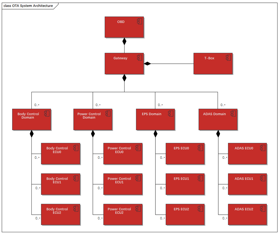
figure 2 - 1 ZC.QingLong OTA System Architecture
With the continuous upgrading of chip technology and OEM OTA specifications, the use of OTA scenarios are also expanding, according to the actual use of scenarios, OTA implementation programs can be divided into the following categories:
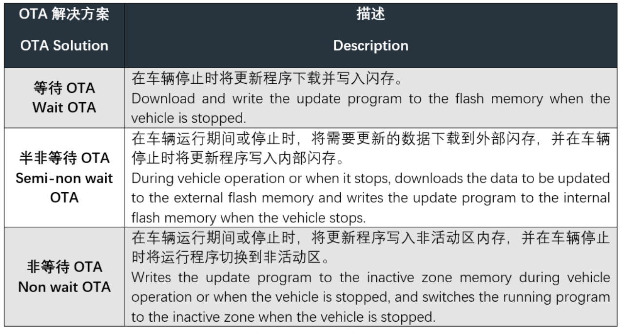
TABLE 2 - 1 OTA Solution
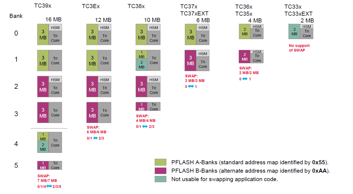
figure 3 - 1 TC3XX AB Bank Assignment
In order to adapt to OTA function and other usage scenarios, most of the chips add support for address mapping function. With the exception of TC33x and TC33xED, all TC3xx chips have the ability to separate PFLASH into two groups of banks, A and B. The address mapping is called “A” in standard address mapping and “B” in alternate address mapping. The group that is active in standard address mapping is called “A” and the group that is active in alternate address mapping is called “B”. One group of PFLASH banks will map to the CPU executable address space (defined as the “active” banks), and the other group will map to a set of addresses that allow reads and writes (defined as the “inactive” banks). When the libraries are swapped after the OTA update is complete, only the address mappings will change, i.e., there is no need to copy the data, and the address ranges will always remain the same at execution time.
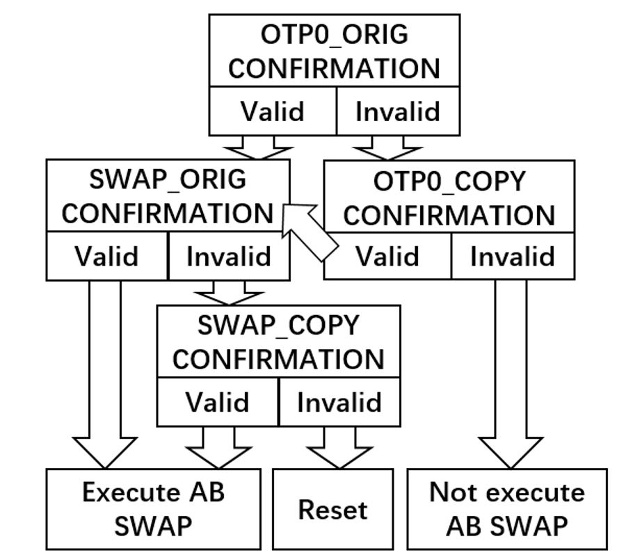
figure 3 - 2 TC3XX AB SWAP startup judgment flowchart
The AB Swap function of the TC3xx is controlled through the UCB registers groups OTPx_ORIG, OTPx_COPY, SWAP_ORIG and SWAP_COPY. The AB Swap function will not be enabled if the enable flag bit of the UCB related register is not set, or the CONFIRMATIONLx and CONFIRMATIONHx register bit data is not valid. The above figure shows the flowchart of AB Swap startup judgment.
The TC3xx performs AB Swap by judging the UCB registers groups SWAP_ORIG and SWAP_COPY. When making judgments, the TC3xx prioritizes the judgments in accordance with the logic in the above figure, and if there are multiple register configurations that meet the judging criteria, the judgment will be made in accordance with the latest set of register configurations.
The UCB register groups SWAP_ORIG and SWAP_COPY contain a total of 16 register configurations, and the functions of each register are shown in the following table:
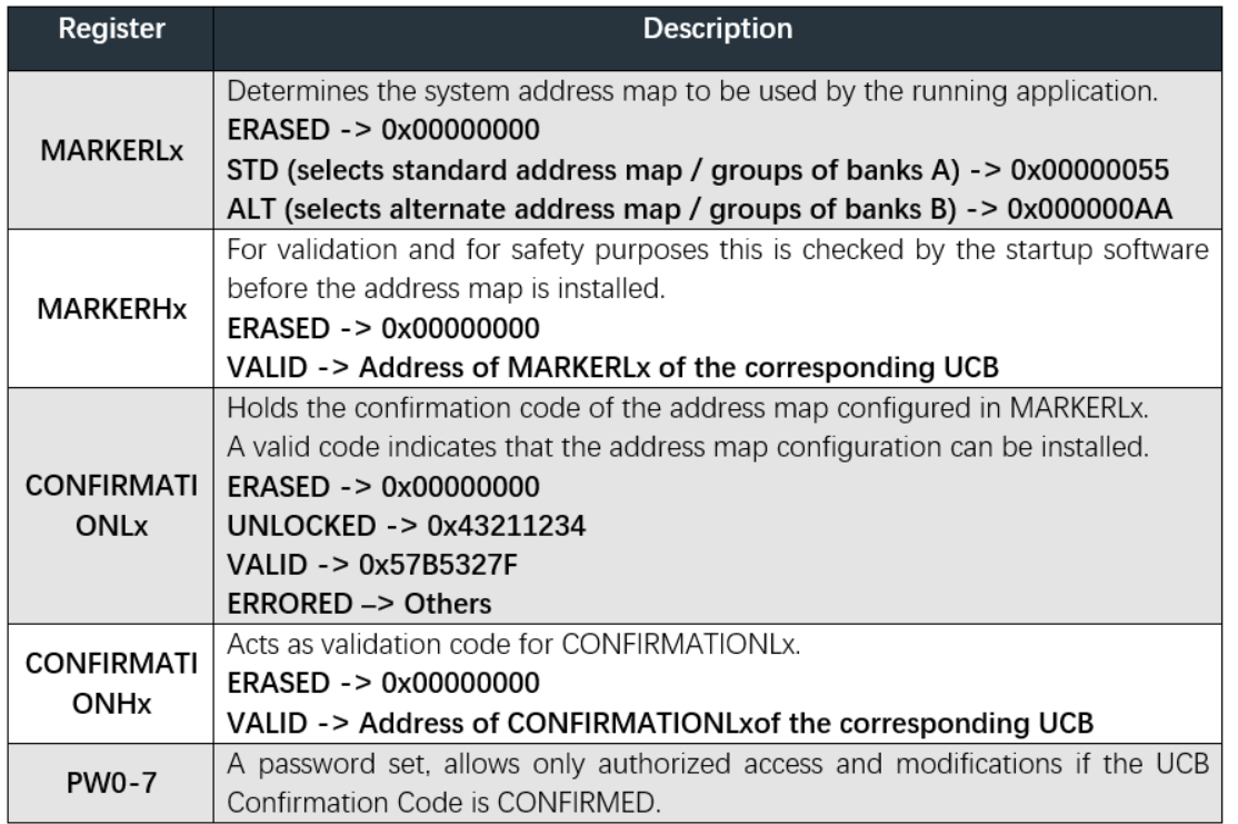
TABLE 3 - 1 Introduction to the SWAP_ORIG and SWAP_COPY register sets
In actual use, the FOTA software needs to determine whether the AB Swap function is enabled or not and whether the AB Swap function performs AB Bank swapping or not after each completion of the software update, and turn on the AB Swap function and switch the partition according to the actual situation, so that the ECU can start from the partition of the update program after reset. The following is the reference configuration of UCB register groups SWAP_ORIG and SWAP_COPY during FOTA execution:
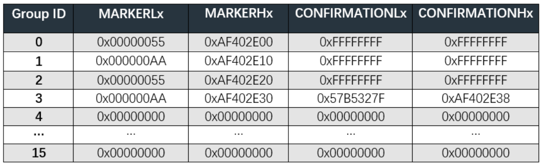
TABLE 3 - 2 SWAP_ORIG register set reference configuration

TABLE 3 - 3 SWAP_COPY register set reference configuration
ZC.Qinglong FOTA realizes the non-wait OTA function by integrating with the application program. The vehicle application software downloads the latest software data while the application software is running by comparing versions, obtaining upgrade tasks, and completing the download automatically. After completing the download, the application software installs the latest software data into the B system. The entire download and installation process is performed while the vehicle is running. Finally, when the vehicle is re-powered, the device performs AB swapping, which is an activation process that can be sensed. For equipment upgrades with non-wait OTA, the only process that is perceived by the user is the “activation” of the new software system. The B-system switchover, which can take up to tens of minutes, can be greatly reduced in the case of non-wait OTA, which can greatly reduce the upgrade time perceivable by the user of the vehicle integrating the complex functions of the domain control equipment, reduce the consumption of vehicle power during the parked upgrade, shorten the time of unavailability of the customer's vehicle, and ensure the availability of the system itself at all times.
The following figure shows the flowchart of programming and AB Swap based on TC397 performed by ZC.QingLong FOTA:
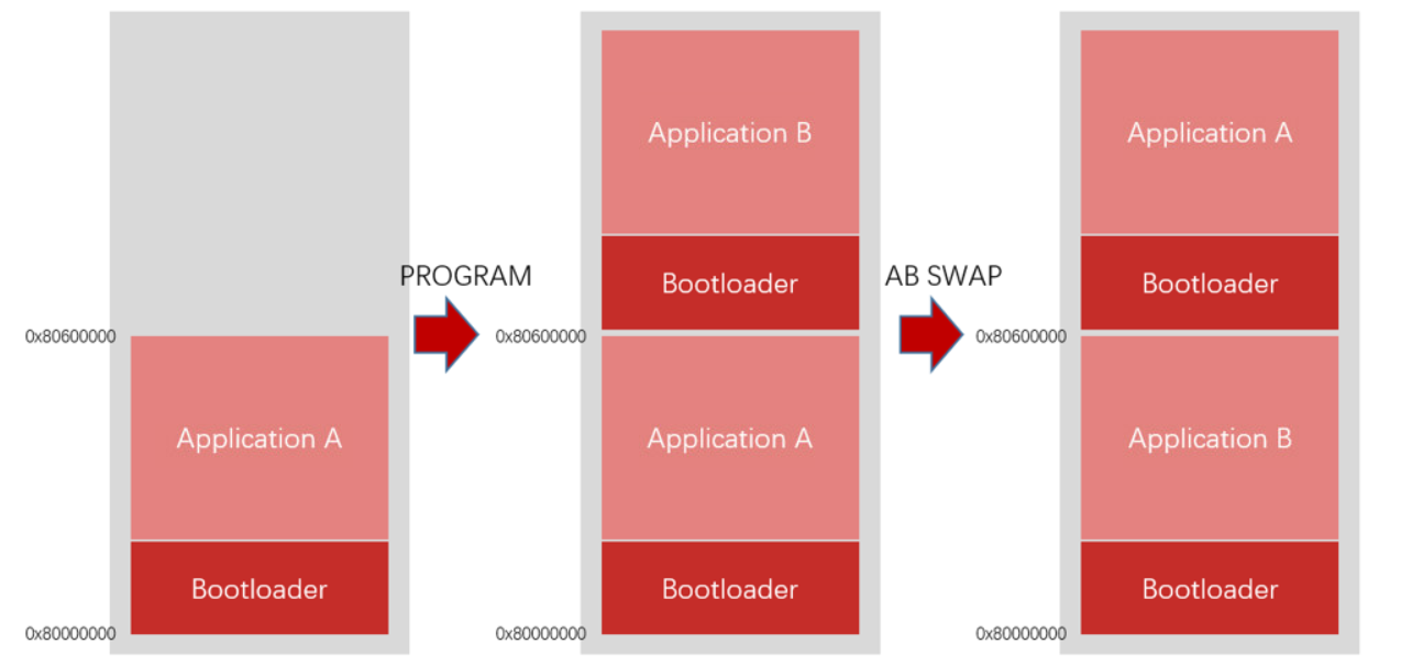
figure 4 - 1 zc.QingLong AB Swap programming squence
