- ZC.MuNiu SafetyLibrary Product Manual Based on Flagchip FC7300
- ZC.MuNiu SafetyLibrary Product Manual Based On Flagchip FC7240
- ZC.MuNiu SafetyFrame Product Manual Based on CYPRESS CYT2B7
- ZC.MuNiu SafetyFrame Product Manual Based on RH850U2AX
- ZC.MuNiu SafetyFrame Product Manual Based on RH850F1KM
- ZC.MuNiu BCC Product Manual Based on NXP MC33771
- ZC.MuNiu SafetyLibrary Product Manual Based on NXP MPC5744P
- ZC.MuNiu SafetyLibrary Product Manual Based on Infineon TC377
- ZC.MuNiu SafetyLibrary Product Manual Based on ST SPC58NH
- Introduction and Usage Methods of Infineon TC3XX MTU Module
- ZC.MuNiu SafetyFrame Product Manual Based on RH850/P1M-C
- ZC.MUNIU SAFETYFRAME PRODUCT MANUAL BASED ON RH850/U2CX
- ZC.MUNIU SAFETYFRAME PRODUCT MANUAL BASED ON FLAGCHIP FC7300F8MDQ
- ZC-YUNTU YTM32B1H/M FUNCTIONAL SAFETY LIBRARY SAFLIB PRODUCT INTRODUCTION
- ZC.MUNIU FUNCTIONAL SAFETY PRODUCT MANUAL BASED ON NXP FS26
- ZC.MUNIU SAFETYFRAME PRODUCT MANUAL BASED ON INFINEON TLE9954
- ZC.MuNiu SafetyLibrary Product Manual Based on ST SPC58NN
- ZC.MuNiu Complex Driver CDD Based on NXP MC33774
- ZC.MuNiu SafetyFrame
- ZC.Muniu SafetyLibrary Product Manual Based On NXP MPC5746C
- ZC.Muniu Saftylibrary Based On NXP MPC5748G
- ZC.MuNiu SafetyLibrary Product Manual Based On NXP S32K14X
- ZC.MuNiu SafetyLibrary Product Manual Based on Infineon TC2XX
- ZC.MuNiu SafetyLibrary Product Manual Based on Infineon TC275
- ZC.MuNiu SafetyLibrary Product Manual Based on Infineon TC397
- ZC.MuNiu SBC Product Manual Based On NXP FS6500-FS4500
- ZC.MuNiu SBC Product Manual Based on Infineon TLF35584
The ZC.MuNiu Functional Safety SBC Series Software is designed to establish ZC Technology's independently developed System Basis Chip (SBC) platform software products that meet customer functional safety requirements, compatible with SBC chips from various manufacturers. This manual details the functional safety application solutions and software architecture based on NXP's FS26 series SBC. This software product enables system engineers and software engineers to rapidly integrate it into customer products, fulfilling functional safety requirements.
The NXP FS26 is an automotive-grade power management IC that integrates multiple switchers, LDOs, high-side drivers (HSDs), low-side drivers (LSDs), and comprehensive safety features. Designed to meet the ISO 26262 ASIL D standard, it is an ideal choice for next-generation critical applications such as automotive domain controllers, ADAS systems, and gateways.
The FS26 chip software driver functionality implemented in this product includes:
• Multi-channel power supply output management;
• SBC state machine control, low-power control, and wake-up management;
• Output voltage diagnostic management;
• SPI communication processing between MCU and SBC;
• SBC on-chip ABIST/LBIST self-test management;
• Watchdog management;
• MCU error monitoring management;
• SBC off-chip secure shutdown path processing.
Introduction to the Watchdog Protocol Stack
In automotive electronic systems, the core objective of Functional Safety is to prevent personal injury or property damage due to electrical and electronic system failures through systematic design and safety mechanisms. WdgM (Watchdog Manager), as a key safety module in the AUTOSAR standard, is designed in strict compliance with the ISO 26262 standard and meets the requirements of different ASIL (Automotive Safety Integrity Level) through multi-layered monitoring, fault tolerance and recovery mechanisms. The WdgM (Watchdog Manager), as a key safety module in the AUTOSAR standard, is designed in strict compliance with ISO 26262 and meets the requirements of different ASIL (Automotive Safety Integrity Level) through multi-level monitoring, fault tolerance and recovery mechanisms.
The main parts of WdgM are the Supervised Entity (SE) and CheckPoint (CP).
l SE: Each SE can have three forms of supervision: Alive, deadline, and Logical [Logical Supervision is divided into two types, program flow supervision within the same SE and program flow supervision within different SEs]. A SE can be an algorithm, a function, a task.
l Check Point : Used as a way to differentiate between different monitoring methods and can belong to one or more of the following types of monitoring methods.
1.1 Alive Supervision
Program Flow Monitoring: The external watchdog implements the WdgM module's Alive Supervision monitoring mechanism to monitor periodic Tasks; the WdgM module calculates the number of checkpoints that occur while the program is running and compares it with the expected value (configuration information), if it is out of tolerance, it is considered as a violation of the program flow, and will be recorded as a Checkpoint Fault by the WdgM module. The WdgM module records this as a checkpoint fault.
Example of Alive Supervision for the AEB module Task:
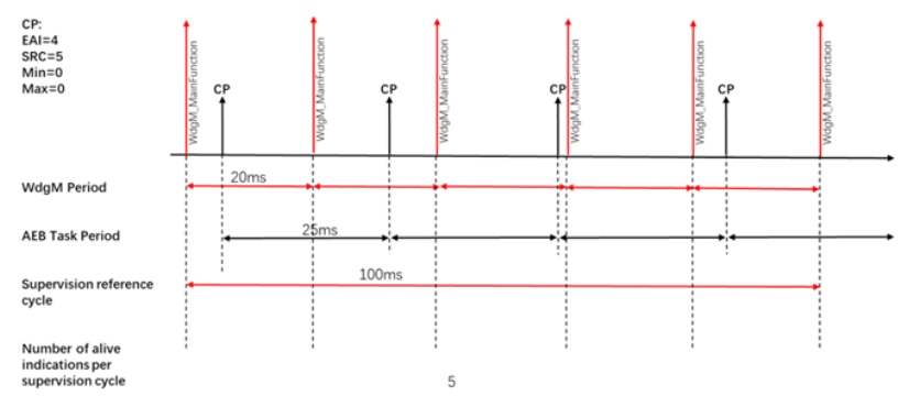
FIGURE 3: Alive supervision
The call cycle of WdgM is 20ms and the cycle of AEB module Task is 25ms, as shown in Figure 6.21, the monitoring cycle is configured to be 100ms, i.e., the number of CheckPoint arrivals in the interval of 5 WdgM_MainFunction is 3-5 as normal. If the number of occurrences is not between 3-5, the WdgM module will consider that the cycle of AEB module Task is detected abnormally, and at the same time, it will transmit the request of not feeding the dog to the PMIC module through the dog feeder data stream shown in Fig. 6.20, and the PMIC module will stop feeding the dog, wait for the timeout of watchdog dog feeder (timeout time of 64ms*3), and then trigger the reset.
1.2 Deadline Supervision
Deadline Supervision is concerned with how long a program is running, whether it is too long or too short indicates that the program is executing abnormally. The abstraction is to monitor the running time between two Check Points. The algorithm is as follows: Configure the Start Check Point, End Check Point, Minimum Time Threshold and Maximum Time Threshold of Deadline Supervision in WdgM. Start Deadline Supervision at the Start Check Point, get the system time, and at the End Check Point, get the system time, and calculate whether the runtime is within the reasonable range.
Note: Two CPs belong to the same SE and two CPs cannot be the same.
1.3 Logical Supervision
Logical Supervision is mainly used to monitor whether the running order of the application is correct or not, including the checking of the local running paths of each SE, and the checking of the global paths between SEs.
Let's say the program runs in the order: 1 -> 2 -> 3 -> 4. When the program reaches 1, it checks to see if it is the first point it should run to, and when it reaches 2, it checks to see if the previous check point reached is 1. In turn, the program checks to see if the actual running order between the two neighboring points matches the running order between the configurations. When the program is run in the order of 1 -> 2 -> 4, a program error is checked at run 4, and the SE status of the Logical Supervison is changed.
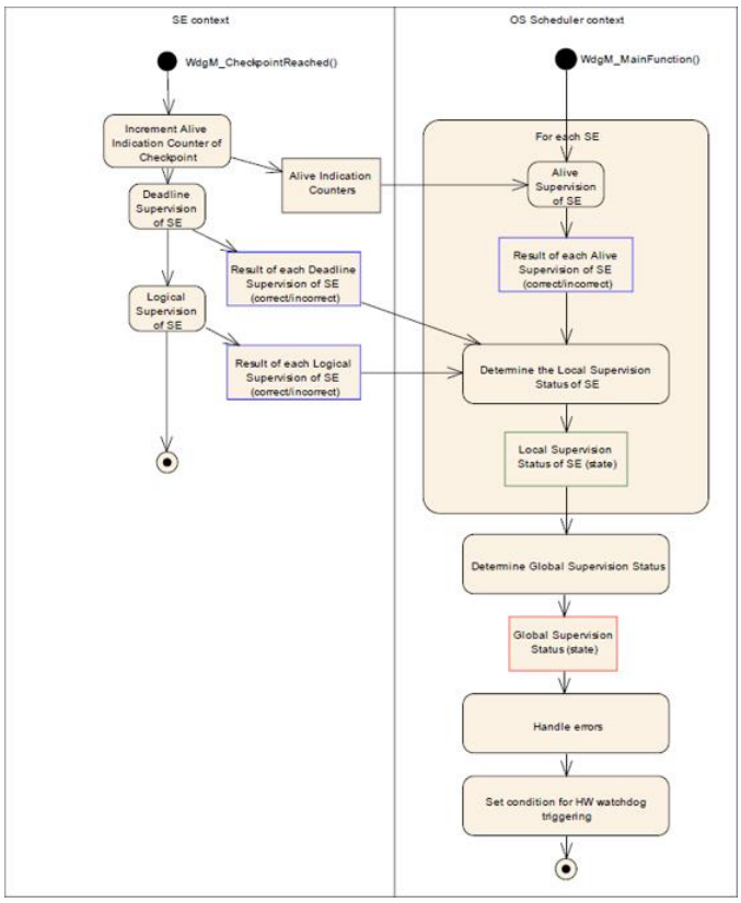
FIGURE 4: Overview of Watchdog Manager Supervision
2 Introduction to ZC.MuNiu
ZC.MuNiu configuration tool is based on the latest ARTOP architecture, supports the latest AUTOSAR R21-11 standard provided by the basic platform, according to the ECU configuration steps defined in the AUTOSAR development methodology, realizes the ECU configuration from the configuration, validation to the code generation of the whole process of the function. The main advantages can be summarized in the following aspects: the realization of the whole process of configuration, verification and code generation has completely realized the development requirements of the ECU configuration stage in the AUTOSAR development methodology.
The following will briefly describe the process of WdgM module configuration using ZC.MuNiu:
2.1 Introduction to WdgM Configuration
2.1.1 Adding SE monitoring instances
You can add monitoring instances related to Alive monitoring through the WdgMMode interface.
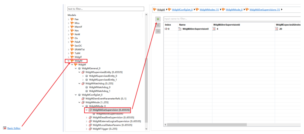
FIGURE 5: MuNiu Supervision Entities Configuration Interface Example1
2.1.2 Configuring SE Punch Points
Multiple SE punch points can be added under the corresponding monitoring instance configuration page.
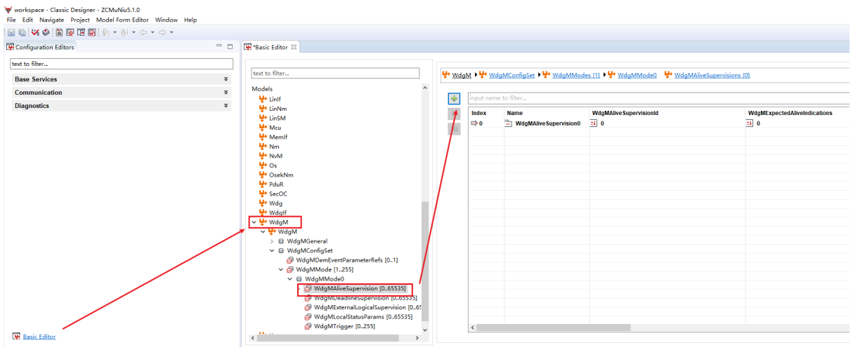
FIGURE 6: MuNiu Checkpoints Configuration Interface Example
In addition, you can set the execution order of punch points in the WdgMInternalTransition page as a way to implement the logic monitoring function.
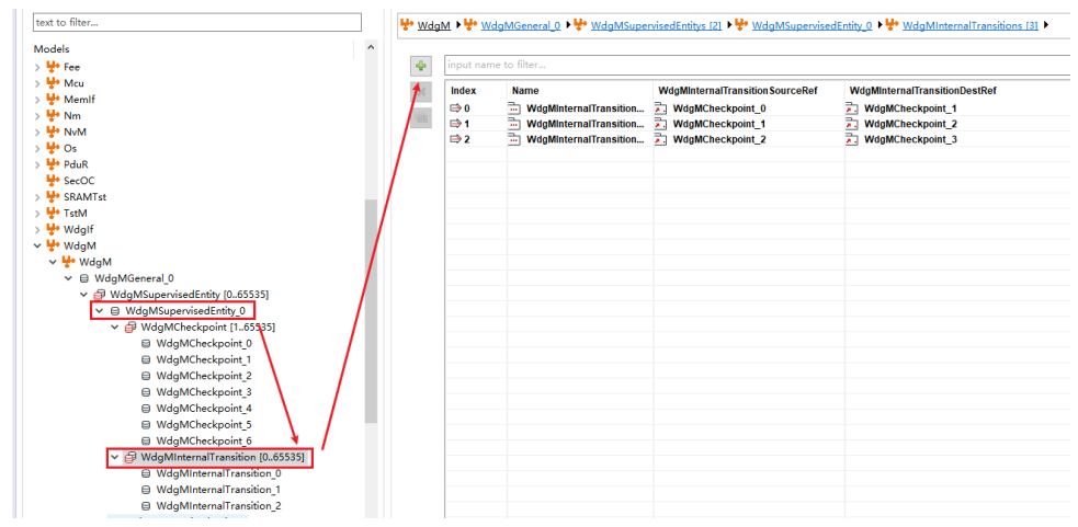
FIGURE 7: MuNiu Internal Transaction Configuration Interface Example
2.1.3 Adding State Parameter Configuration for Monitoring Instances
Under the WdgMAliveSupervision0 page, you can configure the relevant parameters needed for Alive monitoring, such as the monitoring period, the limit of the number of punches that can be tolerated, the monitoring target, and so on.
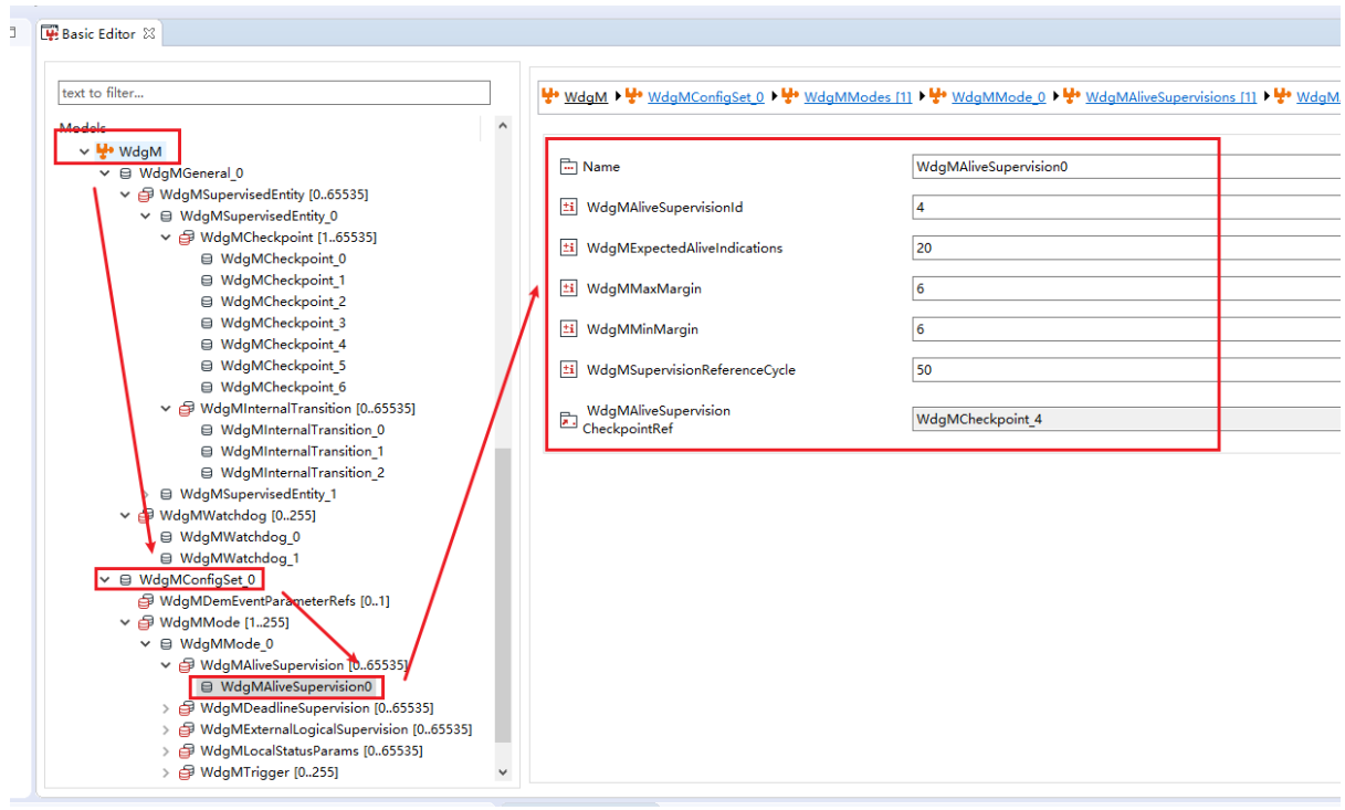
FIGURE 8: MuNiu Alive Supervison Configuration Interface Example
2.1.4 generating configuration code
WdgM related configuration code can be generated after all functions are configured.
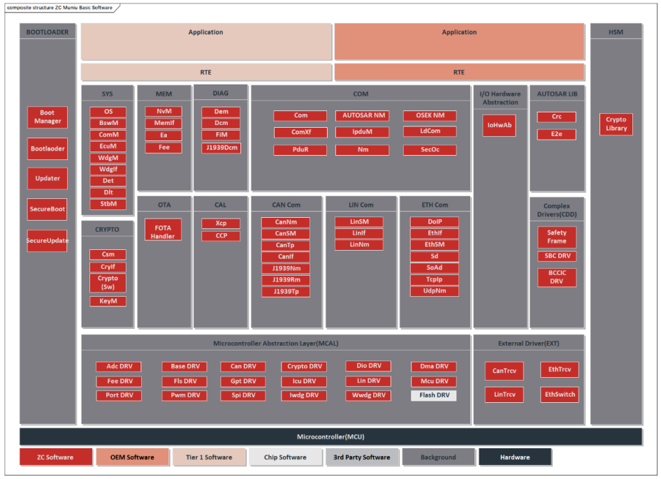
FIGURE 9: MuNiu Code Generation Configuration Interface Example
The SafetyLibrary can be applied to controllers that require functional safety levels.
For example:
Ø Motor Controller
Ø Battery Management System(BMS)
Ø Chassis System Applications
Ø Electronic Stability Control(ESC)
Ø Electric Power Steering(EPS)
Ø Chassis Domain Line Control System Applications
Ø Radar Applications
SPI Periodic Failure Monitoring and Response
This feature enables the MCU to perform active, periodic health checks on the FS26. The MCU reads the FS26's fault status register set via the SPI interface at fixed time intervals (e.g., 10ms), thereby detecting faults such as voltage monitoring anomalies, overheating, watchdog errors, and communication failures in real time. Based on the severity level of the fault, it immediately executes corresponding safety measures.
Software Implementation Process
1. Initialization Phase: Configure FS26's watchdog mode, fault alarm pin (FAILB), and enable each power channel.
2. Scheduled Task Triggering: Periodically initiate monitoring tasks via the MCU's real-time operating system (RTOS) timer or interrupt service routine (ISR).
3. SPI Communication and Reading: The MCU initiates an SPI read sequence to acquire critical register values such as FAIL_STAT_1, FAIL_STAT_2, and DIAG_STAT.
4. Data Verification and Parsing: Perform CRC checks on SPI data to ensure communication integrity, then parse register flags to identify the fault source.
5. Fault Response: Execute corresponding actions based on predefined fault response strategies.
Fault Graded Response Strategy
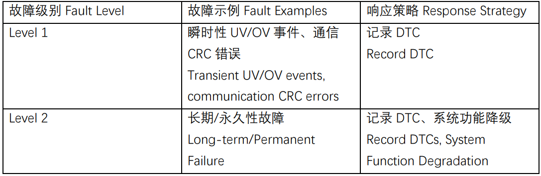

Note: Stop Feeding WDG Mechanism: This represents the highest level of software safety response. When the MCU detects an unhandled critical fault, it proactively halts the refresh of the FS26 watchdog timer. Upon timeout, the FS26 automatically executes its hardware safety response (e.g., triggering a chip reset), ensuring the system forcibly transitions to a known safe state. This is crucial for achieving independence of the safety mechanism.
ABIST Self-Test Function Driver and Diagnostics
1.1 ABIST Function Overview
ABIST (Analog Built-In Self-Test) is an internal self-test function for the FS26's analog module, designed to detect potential defects within the chip.
Ø ABIST1: Rapid self-test with short duration, covering core modules.
Ø ABIST2 (ABIST On Demand): Comprehensive self-test with extended duration, covering all modules.
1.2 Self-Test Triggering Strategy
Ø Ignition On Self-Test: Upon vehicle power-up, a comprehensive ABIST2 self-test is performed before executing primary functions to ensure the FS26 is in a normal initial state.
Ø Periodic Self-Test: During vehicle operation, an ABIST1 rapid self-test is triggered at regular intervals (e.g., every 24 hours) or under specific conditions (e.g., when the vehicle is stationary) to enable online diagnostics while the system is running.
1.3 Self-Test Execution and Result Handling Process
Ø Requesting Self-Test: The MCU initiates the self-test by writing a specific command sequence to the ABIST control register via SPI.
Ø Waiting for Completion: The MCU delays for either t_ABIST1 or t_ABIST2 duration, or polls the DIAG_STAT.ABIST_DONE status bit.
Ø Verify Result: After self-test completion, read the DIAG_STAT.ABIST_PASS bit.
Ø Result Handling:
n Pass: System continues normal operation.
n Fail: Indicates a critical hardware fault. The MCU logs the highest-priority DTC and immediately executes a Level 3 response (stop feeding the dog), transitioning the system to a safe state.
Watchdog Function Overview
Why is the watchdog necessary? The reason is that the software running in the hardware world will be affected by a variety of external factors, such as: many parts and components used in the car, in view of the harsh environment of the car, all types of ECU software may be subjected to such as external electromagnetic interference, high temperature and other environmental factors, which leads to the program “fly” or “dead” phenomenon, at this time, if the existence of the watchdog can actively trigger the system reset mechanism to ensure that it can be used normally again, rather than just watch being watched. “crash” phenomenon, at this time if the existence of the watchdog, you can take the initiative to trigger the system reset mechanism to ensure that it can be used normally again.
Watchdog in use when the software must be in the specified time interval to send a specific signal, this behavior is figuratively known as “feed the dog”, so as to avoid watchdog timeout triggered by the system reboot. Hardware watchdog is generally a specialized chip, which monitors the circuit voltage and current and other indicators to determine whether the system is operating normally. In the following figure is a NXP SBC chip, the chip provides the watchdog function, when using the MCU through the SPI watchdog initialization and feed the dog operation:
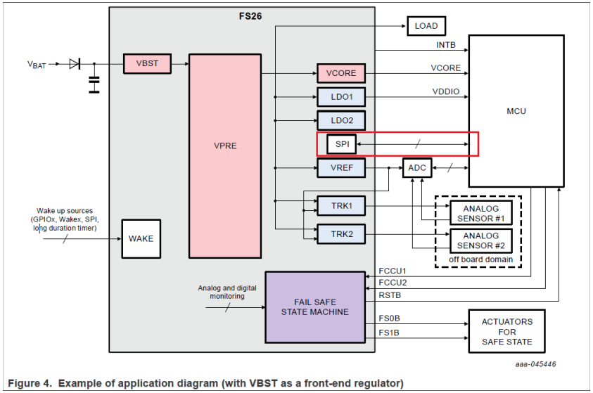
FIGURE 2: external wdg Module
The ZC.MuNiu configuration tool provides a user-friendly HMI for ECU controller software development. It supports the configuration of standard AUTOSAR basic software code modules as well as the development of configuration interfaces for complex drivers. Currently, it is mainly used in the following scenarios:
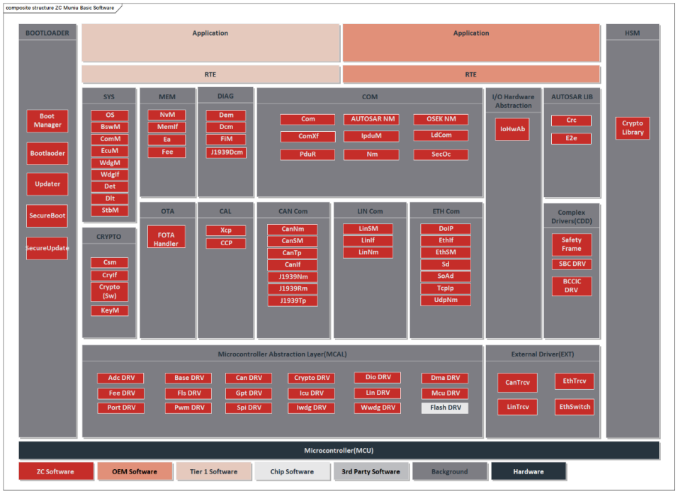
FIGURE 10: MuNiu Standard Platform Block Diagram
Ø ZC.MuNiu Basic Software Platform Standard AUTOSAR Module Configuration
Ø ZC.MuNiu Basic Software Platform Complex Driver Module Configuration
u SAFETY FRAME
u CRYPTO LIBRARY
u BCCIC
u SBC
Ø Collaboration with chip companies to provide configuration tools for MCU MCALs
Currently, the electronic and electrical architecture of automobiles is becoming increasingly complex, and the safety requirements for automotive electronics are also rising. To meet the safety requirements of automobiles, functional safety is gaining more attention. When it comes to functional safety, the first thing that comes to mind is the functional safety standard ISO 26262. In particular, ISO 26262-5(2018) Clause 8 introduces two metrics: Single-point fault metric (single-point fault metric) and Latent-fault metric (latent fault metric). Depending on the required ASIL level, the single-point fault metric and latent fault metric must meet the corresponding levels.
For microcontrollers (MCU, referred to as MCU below), within the electronic and electrical system, they are designed and developed as SEooC (safety element out of context). To meet the aforementioned metric requirements, MCUs need to implement corresponding safety mechanisms. These safety mechanisms can be allocated to both hardware and software modules. The SafLib for MCUs is the implementation of safety mechanisms allocated to software.
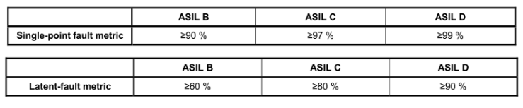
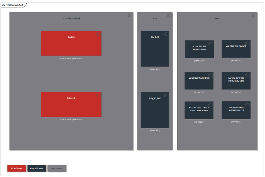
FIGURE 1: SafetyLibrary -FS26 Software Architecture Diagram
Ø Can be integrated as a complex driver into AUTOSAR .
Ø Can be integrated into non-AUTOSAR software architectures.
Ø High Safety: It can achieve up to ASIL-D requirements when paired with SafLib.

Click to download the product manual