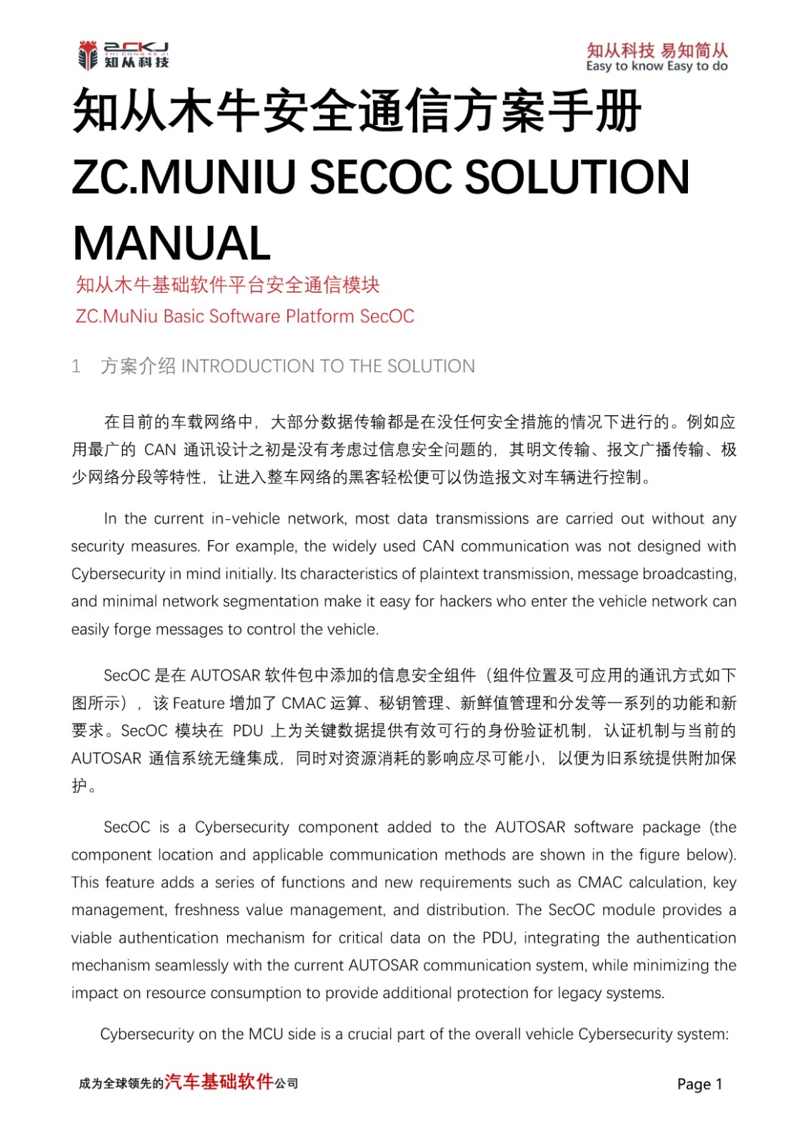
1 前言Introduction
核心价值主张:用一根线,让传感器数据更精准、更可靠、更经济。SENT协议正成为汽车电子领域替代模拟和PWM信号,实现传感器数字化通信的首选方案。
Core Value Proposition: With a single wire, make sensor data more accurate, more reliable, and more cost-effective. The SENT protocol is becoming the preferred solution in the automotive electronics field to replace analog and PWM signals, enabling digital communication for sensors.
随着汽车电动化、智能化浪潮的推进,车载传感器数量呈指数级增长,对数据传输的精度、实时性和可靠性提出了前所未有的要求。传统的模拟电压信号易受干扰,PWM信号的精度和诊断能力有限,而复杂的CAN/LIN总线网络则带来了高昂的成本和布线负担。在此背景下,SENT协议应运而生,为汽车传感器与电子控制单元(ECU)之间的点对点通信提供了最优解决方案。
With the advancement of automotive electrification and intelligentization, the number of onboard sensors has grown exponentially, placing unprecedented demands on data transmission accuracy, real-time performance, and reliability. Traditional analog voltage signals are susceptible to interference, PWM signals have limited accuracy and diagnostic capabilities, and complex CAN/LIN bus networks bring high costs and wiring burdens. In this context, the SENT protocol emerged as the optimal solution for point-to-point communication between automotive sensors and Electronic Control Units (ECUs).
2 技术原理剖析:SENT协议如何实现"以时传数"Technical Principles Analysis: How SENT Protocol Achieves "Data Transmission Through Time"
SENT协议的核心设计哲学在于将信息编码在时间维度而非电压幅度。这种"以时传数"的机制,使其在严苛的汽车电磁环境中展现出卓越的抗干扰能力和高精度特性。
The core design philosophy of the SENT protocol lies in encoding information in the time dimension rather than voltage amplitude. This "data transmission through time" mechanism enables it to demonstrate excellent anti-interference capabilities and high-precision characteristics in harsh automotive electromagnetic environments.
其核心技术架构围绕以下四个关键机制构建:
Its core technical architecture is built around the following four key mechanisms:
1. 时间编码:协议的基本数据单元为"半字节"(Nibble,4位)。每个Nibble的值(0-15)通过测量两个下降沿之间的时间差来编码。具体公式为:脉冲宽度 = (N + 1) × Tick。其中"+1"机制确保了即使传输值为0,脉冲也有最小宽度,增强了信号的鲁棒性。
1. Time Encoding: The basic data unit of the protocol is the "Nibble" (4 bits). Each Nibble value (0-15) is encoded by measuring the time difference between two falling edges. The specific formula is: Pulse Width = (N + 1) × Tick. The "+1" mechanism ensures that even when transmitting a value of 0, the pulse has a minimum width, enhancing signal robustness.
2. 自同步时钟校准:每帧数据以固定56个Tick时长的同步脉冲开始。接收端ECU通过精确测量该同步脉冲的实际物理时间,动态反推出传感器端的Tick周期。这一机制实现了无外部时钟线的动态校准,有效补偿了因温度、电压变化引起的时钟漂移。
2. Self-Synchronizing Clock Calibration: Each data frame begins with a synchronization pulse of fixed 56 Tick duration. The receiving ECU dynamically calculates the sensor-side Tick period by precisely measuring the actual physical time of this synchronization pulse. This mechanism achieves dynamic calibration without external clock lines, effectively compensating for clock drift caused by temperature and voltage variations.
3. 结构化帧传输:一个完整的SENT帧由同步脉冲、状态/通信字、最多6个数据字、CRC校验字和可选的暂停脉冲组成。状态字可携带传感器故障标志或慢速通道数据起始位,数据字则承载核心的传感信息,支持双12位通道传输,CRC校验保障了数据的完整性。
3. Structured Frame Transmission: A complete SENT frame consists of a synchronization pulse, status/communication nibble, up to 6 data nibbles, CRC checksum nibble, and optional pause pulse. The status nibble can carry sensor fault flags or slow channel data start bits, while data nibbles carry core sensor information, supporting dual 12-bit channel transmission. CRC checksum ensures data integrity.
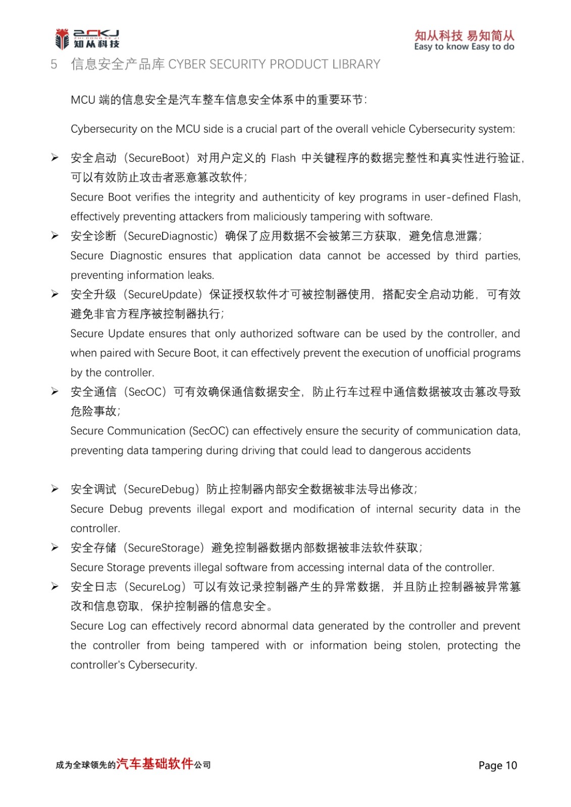
4. 硬件极简主义:发送端(传感器)通常仅需一个精准定时器和一个GPIO引脚,无需专用通信控制器或PHY芯片。接收端(ECU)也仅需一个带输入捕获功能的定时器。这种设计将协议复杂性从遍布车辆的传感器节点转移到了集中的ECU,显著降低了系统整体成本。
4. Hardware Minimalism: The transmitting end (sensor) typically requires only a precision timer and a GPIO pin, without needing dedicated communication controllers or PHY chips. The receiving end (ECU) also requires only a timer with input capture functionality. This design transfers protocol complexity from numerous sensor nodes distributed throughout the vehicle to the centralized ECU, significantly reducing overall system costs.
3 核心优势对比:为什么选择SENT而非传统方案?Core Advantages Comparison: Why Choose SENT Over Traditional Solutions?
为清晰展示SENT协议的全面优势,我们将其与模拟信号、PWM信号及CAN/LIN总线在传感器应用场景下进行多维度对比。
To clearly demonstrate the comprehensive advantages of the SENT protocol, we compare it with analog signals, PWM signals, and CAN/LIN buses in sensor application scenarios across multiple dimensions.
对比维度 | SENT协议 | 模拟信号 | PWM信号 | CAN/LIN |
传输精度 | 高 | 低 | 中 | 高 |
抗干扰能力 | 强 | 弱 | 中等 | 强 |
系统成本 | 低 | 低 | 低 | 中高 |
诊断功能 | 强 | 几乎无 | 弱 | 强 |
实时性 | 高 | 高 | 高 | 中 |
布线复杂度 | 极简 | 简 | 简 | 复杂 |
通过对比可见,SENT协议在精度、抗扰、成本、诊断和实时性五个关键维度上取得了最佳平衡,尤其适合对成本敏感且要求高可靠性的汽车传感器应用。
Through comparison, it is evident that the SENT protocol achieves the optimal balance across five key dimensions: accuracy, anti-interference capability, cost, diagnostics, and real-time performance. It is particularly suitable for automotive sensor applications that are cost-sensitive and require high reliability.
4 关键增强:SPC功能与协议演进Key Enhancement: SPC Functionality and Protocol Evolution
基础SENT协议为单向通信,为满足更复杂的系统需求,SENT SPC应运而生。SPC通过在数据帧的暂停脉冲期间插入主触发脉冲,实现了有限的双向通信和单线多传感器管理。
The basic SENT protocol is unidirectional. To meet more complex system requirements, SENT SPC (Short PWM Code) was developed. SPC achieves limited bidirectional communication and single-wire multi-sensor management by inserting Master Trigger Pulses (MTP) during the pause pulse period of data frames.
SPC功能允许ECU通过发送不同宽度的MTP来"寻址"总线上的特定传感器,从而按需获取数据,可将总线负载降低30%。这使其在需要初始化配置、在线诊断或优先调度关键传感器的场景中价值巨大。
The SPC functionality allows the ECU to "address" specific sensors on the bus by sending MTPs of different widths, thereby obtaining data on demand and reducing bus load by up to 30%. This makes it extremely valuable in scenarios requiring initialization configuration, online diagnostics, or priority scheduling of critical sensors.
5 全景应用:SENT协议赋能现代汽车Panoramic Applications: SENT Protocol Empowering Modern Automobiles
SENT协议已深度渗透到现代汽车的各个核心系统,从传统动力总成到新兴的智能驾驶领域,成为连接物理世界与数字控制的关键桥梁。
The SENT protocol has deeply penetrated various core systems of modern automobiles, from traditional powertrains to emerging intelligent driving fields, becoming a crucial bridge connecting the physical world with digital control.
• 动力总成系统:曲轴/凸轮轴位置传感器、涡轮增压压力传感器、变速箱速度传感器
• Powertrain Systems: Crankshaft/camshaft position sensors, turbocharger pressure sensors, transmission speed sensors
• 底盘与安全系统:轮速传感器(ABS)、加速度传感器、横摆角速度传感器(ESC)
• Chassis and Safety Systems: Wheel speed sensors (ABS), acceleration sensors, yaw rate sensors (ESC)
• 车身电子与新能源:电子油门位置传感器、电池管理系统(BMS)、能量回收系统
• Body Electronics and New Energy: Electronic throttle position sensors, Battery Management Systems (BMS), energy recovery systems
• 智能驾驶:线控转向、线控制动、自动驾驶传感器网络
• Intelligent Driving: Steer-by-wire, brake-by-wire, autonomous driving sensor networks
6 知从科技木牛配置工具对SENT协议的支持ZC.MuNiu Configuration Tool Support for SENT Protocol
6.1 木牛配置工具简介Introduction to MuNiu Configuration Tool
知从科技木牛配置工具是一款专为汽车电子嵌入式软件开发设计的可视化配置工具,深度集成于知从科技基础软件(ZCBasic)生态体系中。该工具基于AUTOSAR架构设计理念,为ECU软件开发提供图形化的配置界面,大幅降低开发门槛,提升开发效率。
The ZC.MuNiu Configuration Tool is a visual configuration tool specifically designed for automotive electronics embedded software development, deeply integrated into the ZC.Basic software ecosystem. Based on AUTOSAR architecture design concepts, it provides a graphical configuration interface for ECU software development, significantly lowering the development threshold and improving development efficiency.
木牛配置工具支持多种车载通信协议的配置与代码生成,包括CAN/CANFD、LIN、FlexRay以及SENT协议。通过可视化的参数配置界面,开发人员可以快速完成协议栈的参数设置、信号映射、诊断配置等复杂工作,自动生成符合标准的配置文件和底层代码,实现"零代码"或"低代码"的协议栈开发。
The MuNiu Configuration Tool supports configuration and code generation for various in-vehicle communication protocols, including CAN/CANFD, LIN, FlexRay, and SENT protocols. Through a visual parameter configuration interface, developers can quickly complete complex tasks such as protocol stack parameter settings, signal mapping, and diagnostic configuration, automatically generating standard-compliant configuration files and low-level code, achieving "zero-code" or "low-code" protocol stack development.
6.2 SENT协议配置功能详解Detailed SENT Protocol Configuration Functions
• 完整的SENT协议栈支持:木牛配置工具完整支持SAE J2716标准定义的SENT协议,包括基础SENT和SPC(Short PWM Code)增强模式,满足不同应用场景的通信需求。
• Complete SENT Protocol Stack Support: The MuNiu Configuration Tool fully supports the SENT protocol as defined by the SAE J2716 standard, including both basic SENT and SPC (Short PWM Code) enhanced modes, meeting communication requirements for different application scenarios.
• 可视化参数配置:通过直观的图形界面配置Tick时间、同步脉冲参数、数据帧格式(Nibble数量)、CRC校验方式等关键参数,避免手动配置的错误。
• Visual Parameter Configuration: Configure key parameters such as Tick time, synchronization pulse parameters, data frame format (number of Nibbles), and CRC checksum methods through an intuitive graphical interface, avoiding manual configuration errors.
• 多通道管理:支持同时配置和管理多个SENT通道,每个通道可独立设置参数,适用于复杂ECU中连接多个传感器的应用场景。
• Multi-Channel Management: Supports simultaneous configuration and management of multiple SENT channels, with each channel independently configurable, suitable for application scenarios in complex ECUs connecting multiple sensors.
• 信号映射与解析:提供可视化的信号映射工具,将SENT帧中的数据Nibble映射到应用层信号,自动完成数据解析和物理值转换配置。
• Signal Mapping and Parsing: Provides visual signal mapping tools to map data Nibbles in SENT frames to application-layer signals, automatically completing data parsing and physical value conversion configuration.
• 诊断与错误处理配置:内置完善的诊断功能配置,包括CRC错误检测、同步脉冲异常检测、时钟漂移监控等,支持用户自定义错误处理策略。
• Diagnostic and Error Handling Configuration: Built-in comprehensive diagnostic function configuration, including CRC error detection, synchronization pulse anomaly detection, clock drift monitoring, etc., supporting user-defined error handling strategies.
• 代码自动生成:基于配置自动生成符合AUTOSAR标准的SENT驱动代码和配置文件,无缝集成到MCAL层,减少90%以上的手动编码工作。
• Automatic Code Generation: Automatically generates AUTOSAR-standard-compliant SENT driver code and configuration files based on configuration, seamlessly integrating into the MCAL layer, reducing manual coding work by over 90%.
6.3 配置界面展示Configuration Interface Display
下图展示了知从科技木牛配置工具的SENT协议配置界面,用户可以通过图形化界面轻松完成协议参数配置:
The following figure shows the SENT protocol configuration interface of the ZC.MuNiu Configuration Tool, where users can easily complete protocol parameter configuration through a graphical interface:
[知从科技木牛配置工具SENT协议配置界面截图]
[Screenshot of ZC.MuNiu Configuration Tool SENT Protocol Configuration Interface]
6.4 典型配置流程Typical Configuration Workflow
1. 通道启用与命名:在配置界面选择SENT模块,启用所需通道并设置通道名称
1. Channel Enable and Naming: Select the SENT module in the configuration interface, enable the required channels, and set channel names.
2. Tick时间配置:根据传感器规格设置Tick时间(通常3-10μs)
2. Tick Time Configuration: Set Tick time according to sensor specifications (typically 3-10μs).
3. 帧格式配置:选择数据Nibble数量(1-6个)、是否使用暂停脉冲
3. Frame Format Configuration: Select the number of data Nibbles (1-6) and whether to use pause pulses.
4. SPC模式配置(可选):如需双向通信,启用SPC模式并配置MTP参数
4. SPC Mode Configuration (Optional): If bidirectional communication is required, enable SPC mode and configure MTP parameters.
5. 信号映射:将SENT数据Nibble映射到应用层信号变量
5. Signal Mapping: Map SENT data Nibbles to application-layer signal variables.
6. 诊断配置:启用CRC校验、同步脉冲监控等诊断功能
6. Diagnostic Configuration: Enable diagnostic functions such as CRC checksum and synchronization pulse monitoring.
7. 代码生成:一键生成配置文件和驱动代码,集成到项目中
7. Code Generation: One-click generation of configuration files and driver code for integration into the project.
7 结语:拥抱SENT,智驭未来Conclusion: Embrace SENT, Drive the Future with Intelligence
在汽车电子向着更智能、更集成、更可靠方向发展的今天,SENT协议在精度、可靠性、成本这个传统的不可能三角中,找到了一个优雅的平衡点。它并非意在取代复杂的CAN或FlexRay网络,而是作为其关键补充,在点对点、高精度、高可靠的传感器通信场景中,提供了无可替代的最优解。
As automotive electronics evolves toward greater intelligence, integration, and reliability today, the SENT protocol has found an elegant balance point in the traditional "impossible triangle" of accuracy, reliability, and cost. It is not intended to replace complex CAN or FlexRay networks, but rather serves as a crucial complement, providing an irreplaceable optimal solution for point-to-point, high-precision, high-reliability sensor communication scenarios.
对于汽车电子工程师而言,掌握并应用SENT协议,意味着能为产品赋予更高的性能、更强的鲁棒性和更优的成本结构。而对于希望在项目中快速落地SENT协议的开发者,知从科技木牛配置工具提供了全方位的技术支持。
For automotive electronics engineers, mastering and applying the SENT protocol means endowing products with higher performance, stronger robustness, and better cost structures. For developers seeking to rapidly implement the SENT protocol in their projects, the ZC.MuNiu Configuration Tool provides comprehensive technical support.
知从科技木牛配置工具核心优势
Core Advantages of ZC.MuNiu Configuration Tool
★ 开箱即用:完整的SENT协议栈支持,无需从零开发,缩短项目周期50%以上
★ Ready to Use: Complete SENT protocol stack support, no need to develop from scratch, reducing project cycle by over 50%.
★ 可视化配置:直观的图形界面,大幅降低协议配置复杂度,减少人为错误
★ Visual Configuration: Intuitive graphical interface, significantly reducing protocol configuration complexity and human errors.
★ AUTOSAR兼容:生成符合AUTOSAR标准的代码和配置,无缝集成主流AutoSAR工具链
★ AUTOSAR Compatible: Generates AUTOSAR-standard-compliant code and configuration, seamlessly integrating with mainstream AUTOSAR toolchains.
★ 一站式服务:从配置到代码生成、从调试到验证,提供全流程技术支持
★ One-Stop Service: From configuration to code generation, from debugging to verification, providing full-process technical support.
★ 持续更新:紧跟SAE标准演进,持续更新协议支持,保障技术领先性
★ Continuous Updates: Following SAE standard evolution, continuously updating protocol support to ensure technological leadership.
★ 本土化支持:国内专业团队提供及时的技术支持和服务响应
★ Localized Support: Domestic professional teams provide timely technical support and service response.
 收起
收起
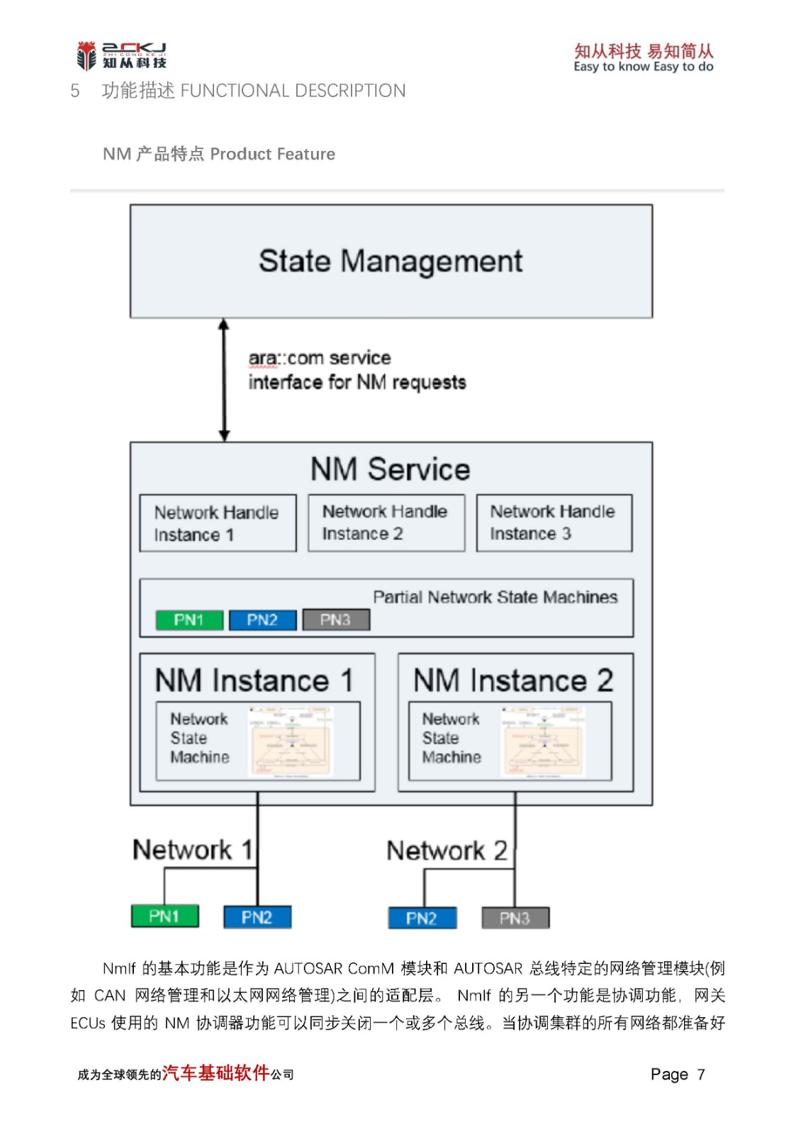
1 功能概述functional overview
知从木牛基础软件平台( ZC.MuNiu )为汽车电子控制器产品开发,提供完整的基础软件平台解决方案。该产品参考AUTOSAR、OSEK等国际规范。有基于AUTOSAR ARTOP架构的上位机配置工具,支持上汽、一汽、吉利、广汽、长安、长城等整车厂通讯、诊断、网络管理规范。
ZC.MuNiu provides a comprehensive basic software platform solution for the development of automotive electronic control units. This product refers to international standards such as AUTOSAR and OSEK, and has a configuration tool based on the AUTOSAR ATOP architecture that supports communication, diagnostics, and network management specifications for major OEMs like SAIC Motor, FAW, Geely, GAC Group, Changan Automobile, and Great Wall Motors.
知从木牛基础软件平台,主要包括:操作系统、通讯协议栈(CAN\ LIN)、诊断协议栈(UDS\OBD\J1939)、网络管理(OSEK\AUTOSAR)、标定协议栈(XCP\CCP)、存储协议栈、加密模块(CRYPTO)、复杂驱动等模块,配套知从的Bootloader刷新程序和上位机工具,可以根据不同的客户项目要求进行配置和再开发。知从科技提供基础软件产品的同时,也提供控制器基础软件功能实现的开发服务。
The platform mainly includes: operating system, communication protocol stack (CAN/LIN), diagnostic protocol stack (UDS/J1939), network management (OSEK/AUTOSAR), calibration protocol stack (XCP/CCP), storage protocol stack, complex driver modules, etc., along with ZC 's bootloader update program and configuration tool, which can be configured and redeveloped according to different customer project requirements. While providing basic software products, ZC also offers development services for the implementation of controller basic software functions.
CanIf模块将底层不同的Can驱动,CanTrcv驱动抽象化,方便上层模块统一通过CanIf模块进行访问。在AUTOSAR架构中,其上层模块主要为PduR,CanTp,J1939Tp,CanNm,CanSm等。CanIf主要功能包含L-PDU的接收指示,L-PDU的发送及发送确认等通信功能, 以及Can Controller/Trcv的模式控制,波特率切换,睡眠唤醒等其它功能栈功能。
The CanIf module abstracts different underlying Can and CanTrcv drivers, facilitating unified access by upper-layer modules through the CanIf module. In the AUTOSAR architecture, the upper-layer modules mainly include PduR, CanTp, J1939Tp, CanNm, CanSm, etc. The main functions of CanIf include communication functions such as L-PDU reception indication, L-PDU transmission and transmission confirmation,as well as CAN controller/Trcv management, covering mode control, baud rate switching, and sleep/wake-up capabilities.
2 应用领域APPLICATION FIELD
Ø 发动机管理系统(EMS)
Engine Management System (EMS)
Ø 变速器控制器(TCU)
Transmission Control Unit (TCU)
Ø 制动控制器(BCU)
Brake Control Unit (BCU)
Ø 电机控制器(MCU)
Motor Control Unit (MCU)
Ø 电子驻车系统(EPB)
Electronic Parking Brake (EPB)
Ø 电池管理系统控制器(BMS)
Battery Management System (BMS)
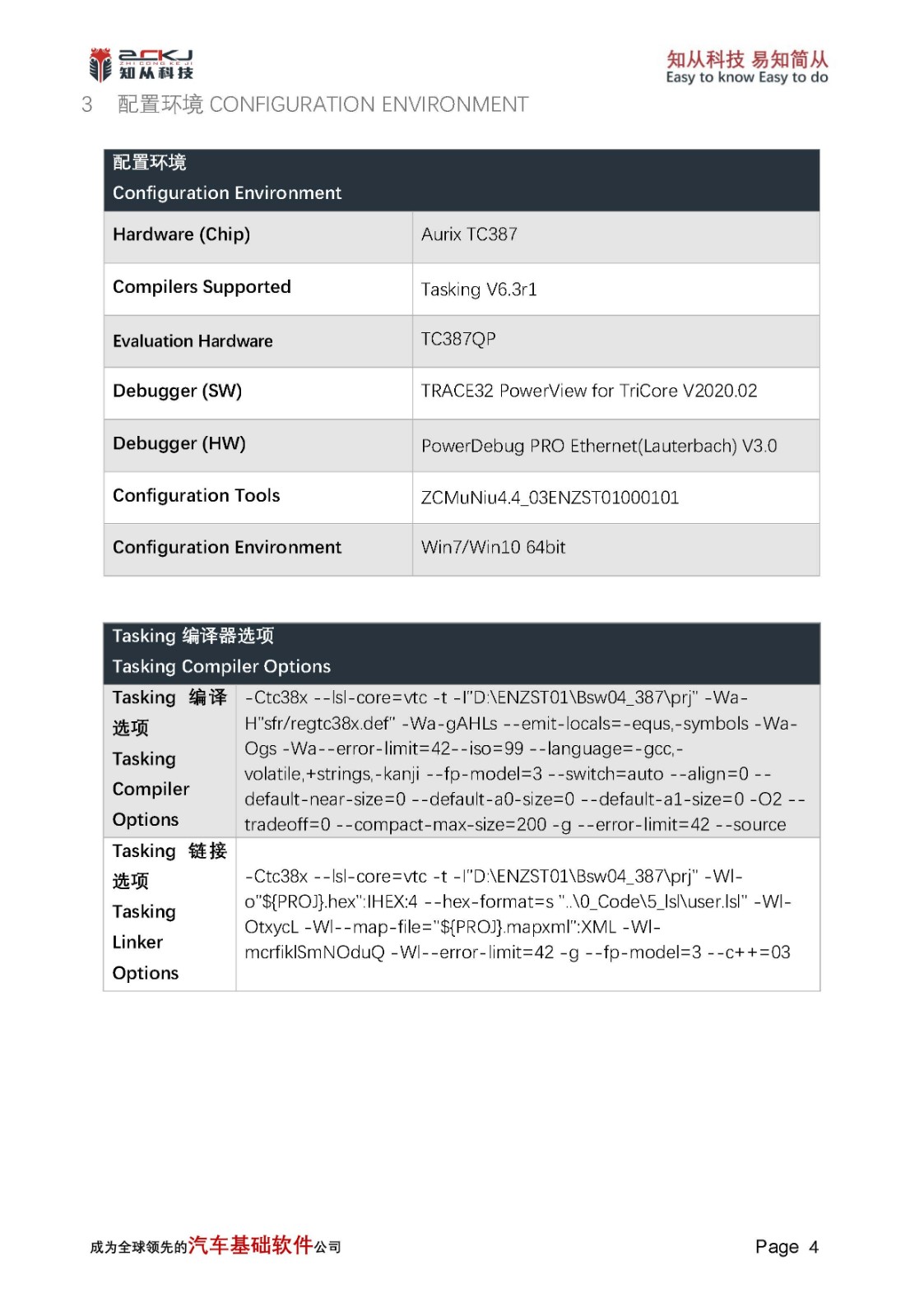
3 配置环境CONFIGURATION ENVIRONMENT
配置环境 Configuration Environment | |
Hardware (Chip) | Aurix TC387 |
Compilers Supported | Tasking V6.3r1 |
Evaluation Hardware | TC387QP |
Debugger (SW) | TRACE32 PowerView for TriCore V2020.02 |
Debugger (HW) | PowerDebug PRO Ethernet(Lauterbach) V3.0 |
Configuration Tools | ZCMuNiu4.4_03ENZST01000101 |
Configuration Environment | Win7/Win10 64bit |
Tasking编译器选项 Tasking Compiler Options | |
Tasking编译选项 Tasking Compiler Options | -Ctc38x --lsl-core=vtc -t -I"D:\ENZST01\Bsw04_387\prj" -Wa-H"sfr/regtc38x.def" -Wa-gAHLs --emit-locals=-equs,-symbols -Wa-Ogs -Wa--error-limit=42--iso=99 --language=-gcc,-volatile,+strings,-kanji --fp-model=3 --switch=auto --align=0 --default-near-size=0 --default-a0-size=0 --default-a1-size=0 -O2 --tradeoff=0 --compact-max-size=200 -g --error-limit=42 --source |
Tasking链接选项 Tasking Linker Options | -Ctc38x --lsl-core=vtc -t -I"D:\ENZST01\Bsw04_387\prj" -Wl-o"${PROJ}.hex":IHEX:4 --hex-format=s "..\0_Code\5_lsl\user.lsl" -Wl-OtxycL -Wl--map-file="${PROJ}.mapxml":XML -Wl-mcrfiklSmNOduQ -Wl--error-limit=42 -g --fp-model=3 --c++=03 |
4 开发背景 DEVELOPMENT BACKGROUND
AUTOSAR组织成立于2003年,主要由欧洲汽车制造商、部件供应商及其他电子、半导体和软件系统公司联合建立。致力于为汽车工业开发一个开放的、标准化的软件架构;希望大家“在标准上合作,在应用上竞争”提高基础平台的稳定,降低成本,提高控制器产品开发质量和速度。2006年底发布了2.1版规范,2008年发布3.1版本开始产品化;后续逐步增加了功能安全,以太网等内容,目前广泛使用2014年后发布的4.2.1和4.2.2版本,以及4.3.1版本。
The AUTOSAR organization was established in 2003, mainly by European car manufacturers, component suppliers, and other electronics, semiconductor, and software system companies. It is committed to developing an open, standardized software architecture for the automotive industry; the goal is for everyone to "cooperate on standards and compete on applications," improving the stability of the basic platform, reducing costs, and enhancing the quality and speed of controller product development. The 2.1 version of the specification was released at the end of 2006, and the 3.1 version was released in 2008 for productization; subsequently, functional safety, Ethernet, and other contents were gradually added. Currently, the widely used versions are 4.2.1 and 4.2.2 released after 2014, as well as version 4.3.1
知从.木牛( ZC.MuNiu )为汽车电子控制器产品开发,提供完整的基础软件平台解决方案。该产品符合AUTOSAR、OSEK等国际规范,有基于AUTOSAR ARTOP架构的上位机配置工具,支持上汽、一汽、吉利、广汽、长安、长城等整车厂通讯、诊断、网络管理规范。该平台主要包括:操作系统、通讯协议栈(CAN\ LIN)、诊断协议栈(UDS\OBD\J1939)、网络管理(OSEK\AUTOSAR)、标定协议栈(XCP\CCP)、存储协议栈、加密模块(CRYPTO)、复杂驱动等,配套知从Bootloader刷新程序和上位机工具,可以根据不同的客户项目要求进行配置和再开发。
ZC.MuNiu provides a comprehensive basic software platform solution for the development of automotive electronic control unit products. This product complies with international standards such as AUTOSAR and OSEK, and features a configuration tool based on the AUTOSAR ATOP architecture, supporting communication, diagnostics, and network management specifications for major vehicle manufacturers like SAIC Motor, FAW, Geely, GAC Group, Changan Automobile, and Great Wall Motors. The platform mainly includes: operating system, communication protocol stack (CAN/LIN), diagnostic protocol stack (UDS/J1939), network management (OSEK/AUTOSAR), calibration protocol stack (XCP/CCP), storage protocol stack, complex driver modules, etc. It is equipped with ZC 's bootloader update program and upper computer tool, which can be configured and redeveloped according to different customer project requirements.
知从科技提供基础软件产品的同时,也提供符合ASPICE Level2和功能安全ASILB\D要求的控制器基础软件功能实现的开发服务,以及SBC芯片等软件的定制开发。
ZC not only provides basic software products but also offers development services for the implementation of control unit basic software functions that comply with ASPICE Level 2 and functional safety requirements ASIL B/D. In addition, it provides customized software development for SBC (Safety-Critical Base Control) chips and similar components.
知从科技掌握AUTOSAR平台软件的开发和应用核心技术,提供本地现场支持,质量好,速度快,成本低。
ZC has mastered the core technology of development and application of the AUTOSAR platform software, providing on-site local support with high quality, fast speed, and low cost.
5 功能描述FUNCTIONAL DESCRIPTION
5.1 CAN 协议栈Protocol Stack
CanIf模块的状态机控制,包括未初始化和已初始化状态,除了CanIf_Init 和CanIf_GetVersionInfo之外,都需要在已初始化状态下才能正常调用。
The state machine control of the CanIf module includes UNINITIALIZED and INITIALIZED states. With the exception of CanIf_Init and CanIf_GetVersionInfo, all other API functions require the module to be in the INITIALIZED state for proper operation.
Controller模式控制,分为STOPPED,STARTED,SLEEP三种,只有在START状态下Controller才能正常通信。Trcv模式控制,分为NORMAL,STANDBY,SLEEP三种,只有在NORMAL状态下Trcv才能正常通信。Controller的Pdu模式控制,分为OFFLINE,TX_OFFLINE,TX_OFFLINE_ACTIVE,ONLINE四种, ONLINE模式下允许正常收发通信,TX_OFFLINE模式下只能接收不能发送, TX_OFFLINE_ACTIVE模式下允许接收和虚拟发送,OFFLINE模式下不允许收发通信。
The Controller supports three modes: STOPPED, STARTED, and SLEEP. Normal communication is possible only when the Controller is in the STARTED state. Trcv supports three modes: NORMAL, STANDBY, and SLEEP. Normal communication is possible only when Trcv is in the NORMAL state. The Controller supports four PDU modes: OFFLINE, TX_OFFLINE, TX_OFFLINE_ACTIVE, and ONLINE. In the ONLINE mode, both transmission and reception are allowed; in the TX_OFFLINE mode, only reception is allowed and transmission is not permitted; in the TX_OFFLINE_ACTIVE mode, reception and virtual transmission are allowed; in the OFFLINE mode, both transmission and reception are not allowed.
CAN协议栈具有以下特点:
The CAN protocol stack has the following characteristics:
Ø TxPdu发送功能:TxPdu Transmission Function:
当模块初始化成功,Controller模式及其Pdu模式,Trcv模式均处于允许发送状态时,可通过CanIf两种发送机制来发送L-Pdu: 上层模块调用CanIf_Transmit请求TxPdu的发送,发送时机由上层决定;下层驱动调用CanIf_TriggerTransmit请求TxPdu的发送数据,发送时机由下层决定;
When the module is successfully initialized and the Controller, PDU, and Trcv modes all enter a transmit-enabled state, L-PDUs can be sent using either of the two transmission mechanisms provided by CanIf: The upper-layer module calls CanIf_Transmit to request the transmission of TxPdu. The transmission timing is determined by the upper layer. The lower-layer driver calls CanIf_TriggerTransmit to request TxPDU data for transmission. The transmission timing is determined by the lower layer.
Ø RxPdu接收功能:RxPdu Reception Function:
当模块初始化成功,Controller模式及其Pdu模式,Trcv模式均处于允许接收状态时,将从驱动层接收到的报文,传递到上层模块。当驱动层邮箱收到报文后,调用CanIf_RxIndication将接收数据传递到CanIf模块,CanIf通过接收的HRH以及CanId, 查询匹配到接收RxPdu,调用关联上层模块的
When the module is successfully initialized and the Controller, PDU, and Trcv modes all enter a receive-enabled state, any messages received from the driver layer will be passed up to the upper-layer module. When a message is received in the driver layer's mailbox, it invokes CanIf_RxIndication to deliver the data to the CanIf module. Using the received HRH and CanId, CanIf looks up the matching Rx PDU and then calls the corresponding
Ø 睡眠唤醒功能:Sleep and Wake-up Function:
上层模块可以通过CanIf来将Controller/Trcv设置为SLEEP模式,支持Controller/Trcv唤醒源检测,Controller/Trcv唤醒确认,Trcv唤醒原因获取,Trcv唤醒标志位检测/清除,Trcv唤醒模式设置。CanIf提供CanIf_SetControllerMode/CanIf_SetTrcvMode来设置Controller/Trcv的模式(包含SLEEP模式), 当发生唤醒事件后可通过调用CanIf_CheckWakeup来检测是否由Controller/Trcv导致的唤醒事件, 可通过CanIf_CheckValidation来检测唤醒成功确认(唤醒确认条件为接收到任意Pdu/NM Pdu, 参见配置项CanIfPublicWakeupCheckValidByNM是否勾选)。
The upper-layer module can set the Controller/Trcv to SLEEP mode through CanIf. CanIf supports Controller/Trcv wake-up source detection, Controller/Trcv wake-up confirmation, Trcv wake-up reason retrieval, Trcv wake-up flag detection/clearance, and Trcv wake-up mode setting. CanIf provides CanIf_SetControllerMode/CanIf_SetTrcvMode to set the mode of Controller/Trcv (including SLEEP mode). When a wake-up event occurs, CanIf_CheckWakeup can be called to detect whether the event is caused by the Controller/Trcv. CanIf_CheckValidation can be used to confirm the wake-up (a wake-up is confirmed upon receipt of any Pdu/NM Pdu, see whether the configuration item CanIfPublicWakeupCheckValidByNM is checked).
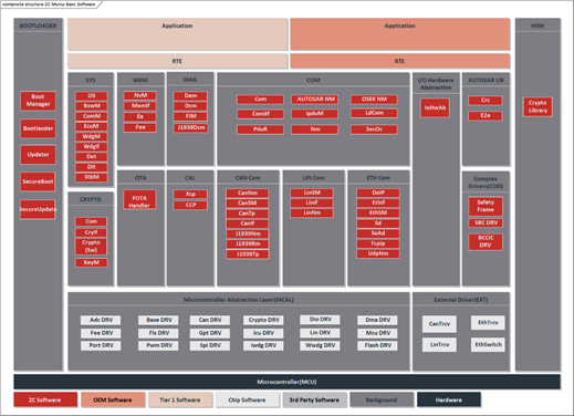
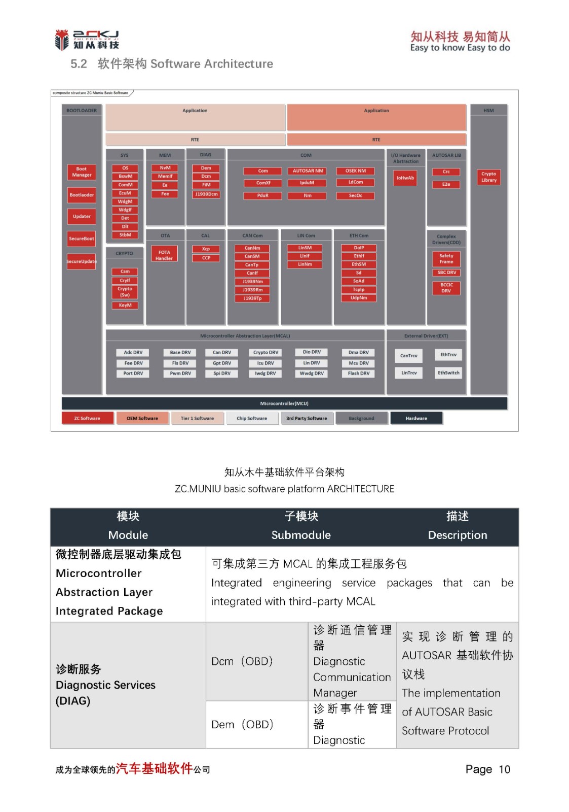
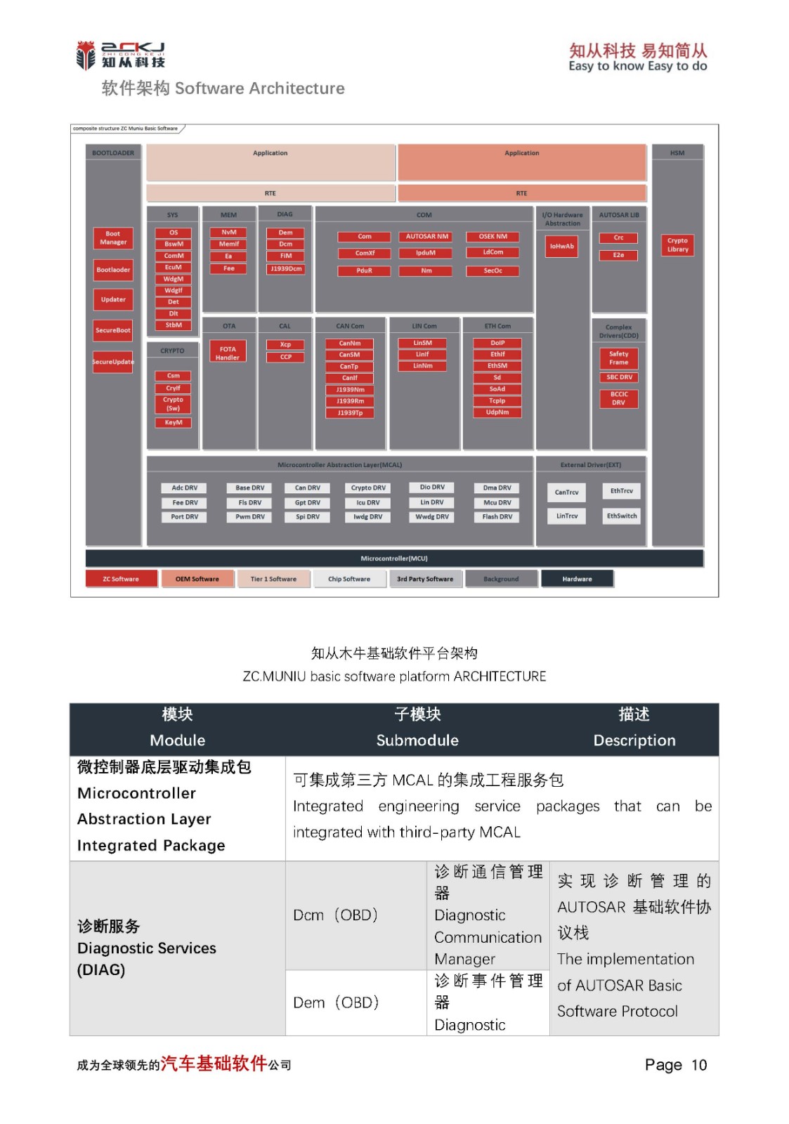
5.2 软件架构 Software Architecture

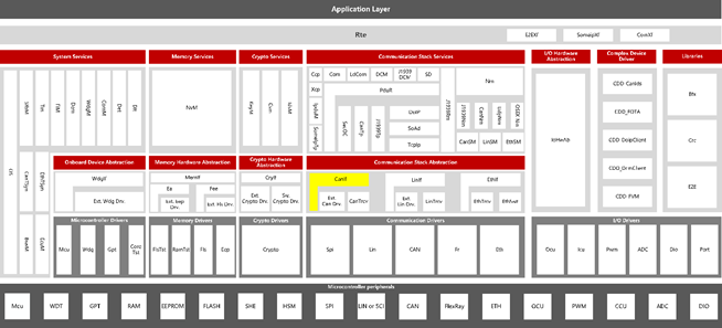
知从木牛基础软件平台架构
ZC.MUNIU basic software platform ARCHITECTURE
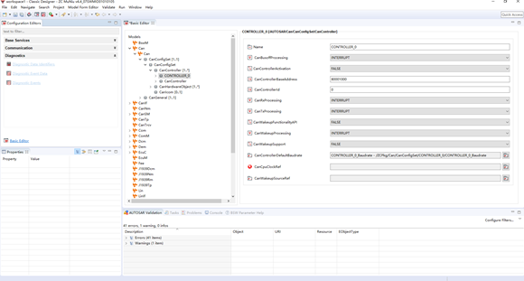
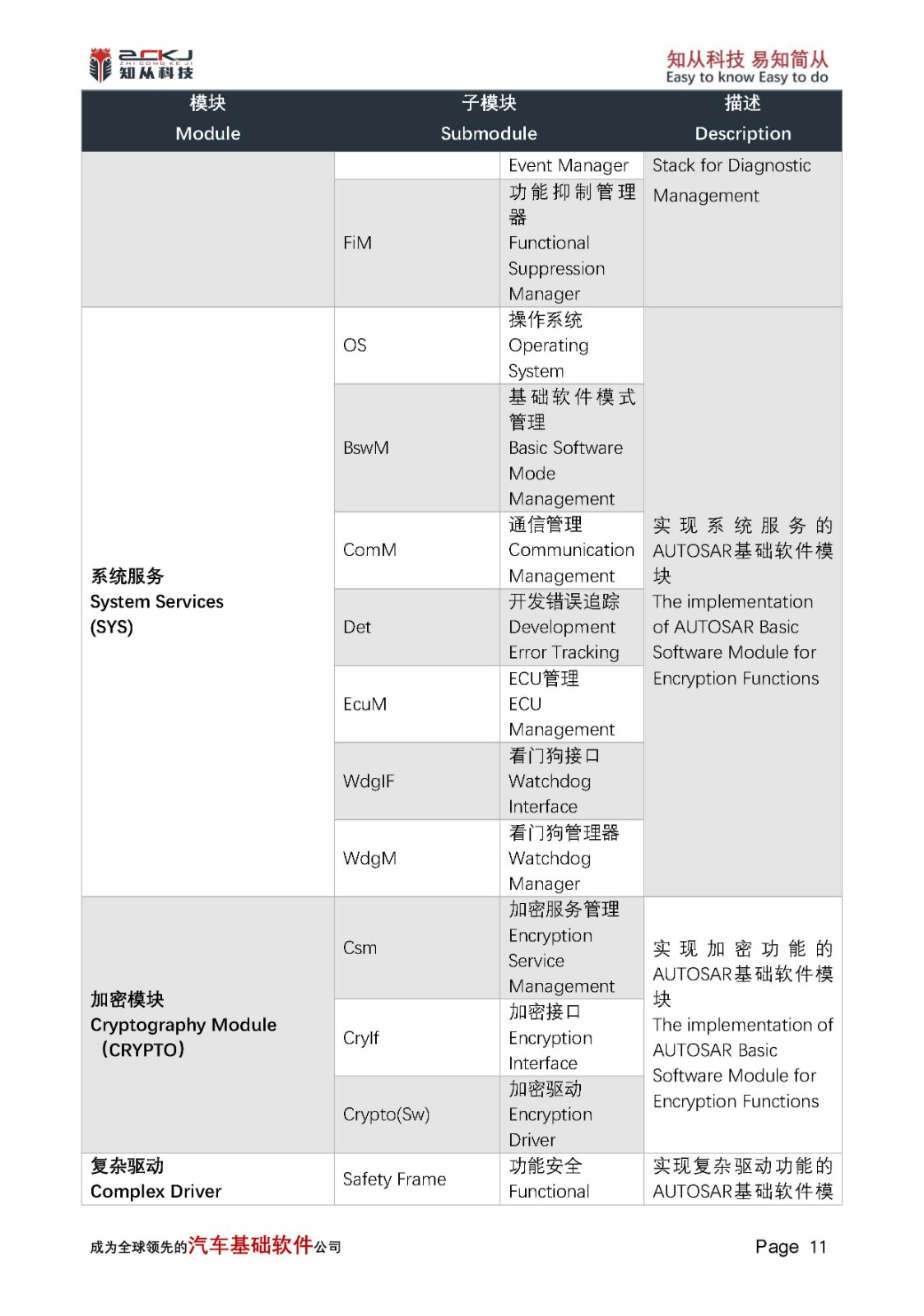
5.3 配置工具Configuration Tool
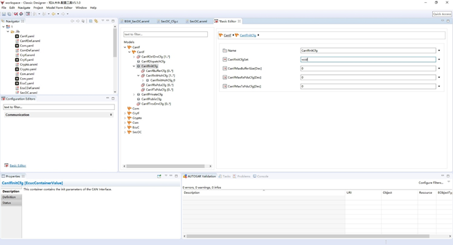
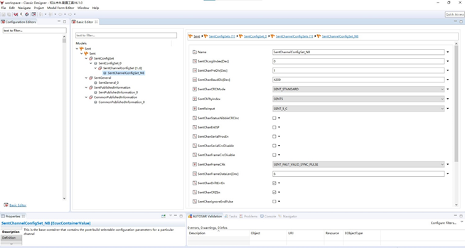
木牛配置工具主界面
MUNIU CONFIGURATION TOOL MAIN INTERFACE
为了满足客户的不同项目需求,提高基础软件平台的扩展性, 木牛基础软件平台实现了各个模块可配置性,并且实现了配置工具。客户可根据不同需求,在配置工具上完成各个模块的配置工作,可生成配置代码文件,将生成的配置文件集成到工程中即可。
To meet the diverse project requirements of our clients and enhance the extensibility of the basic software platform, ZC.MuNiu Basic Software Platform has implemented configurable modules and a configuration tool. Customers can use the configuration tool to tailor the modules according to their specific needs, generate configuration code files, and integrate these generated configuration files into their projects. This approach allows for a high degree of customization and adaptability, ensuring that the software platform can be easily adapted to various applications and use cases.
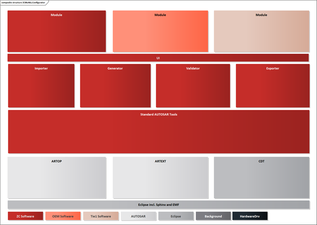
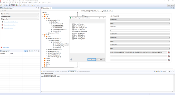
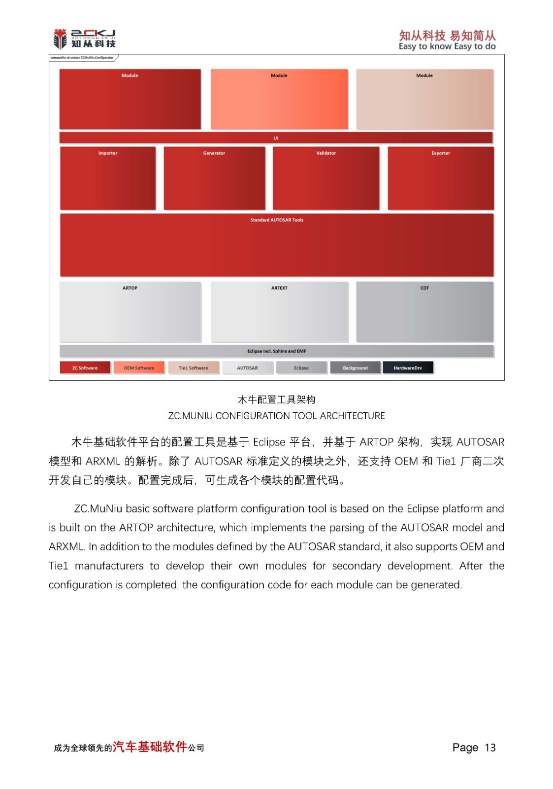
木牛配置工具架构
ZC.MUNIU CONFIGURATION TOOL ARCHITECTURE
木牛基础软件平台的配置工具是基于Eclipse平台,并基于ARTOP架构,实现AUTOSAR模型和ARXML的解析。除了AUTOSAR标准定义的模块之外,还支持OEM和Tie1厂商二次开发自己的模块。配置完成后,可生成各个模块的配置代码。
ZC.MuNiu basic software platform configuration tool is based on the Eclipse platform and is built on the ARTOP architecture, which implements the parsing of the AUTOSAR model and ARXML. In addition to the modules defined by the AUTOSAR standard, it also supports OEM and Tie1 manufacturers to develop their own modules for secondary development. After the configuration is completed, the configuration code for each module can be generated.
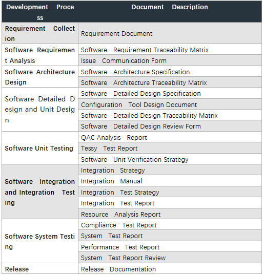
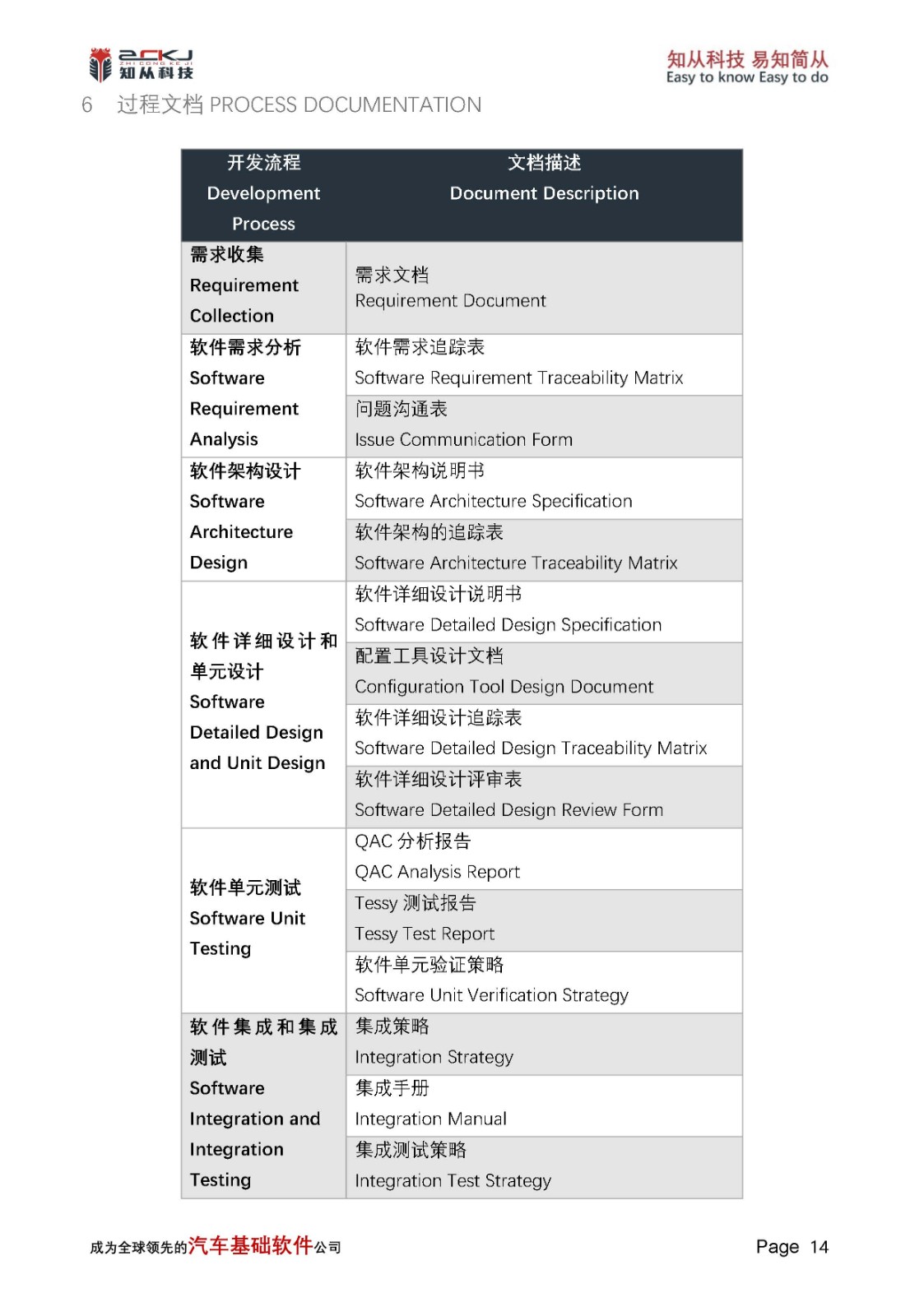
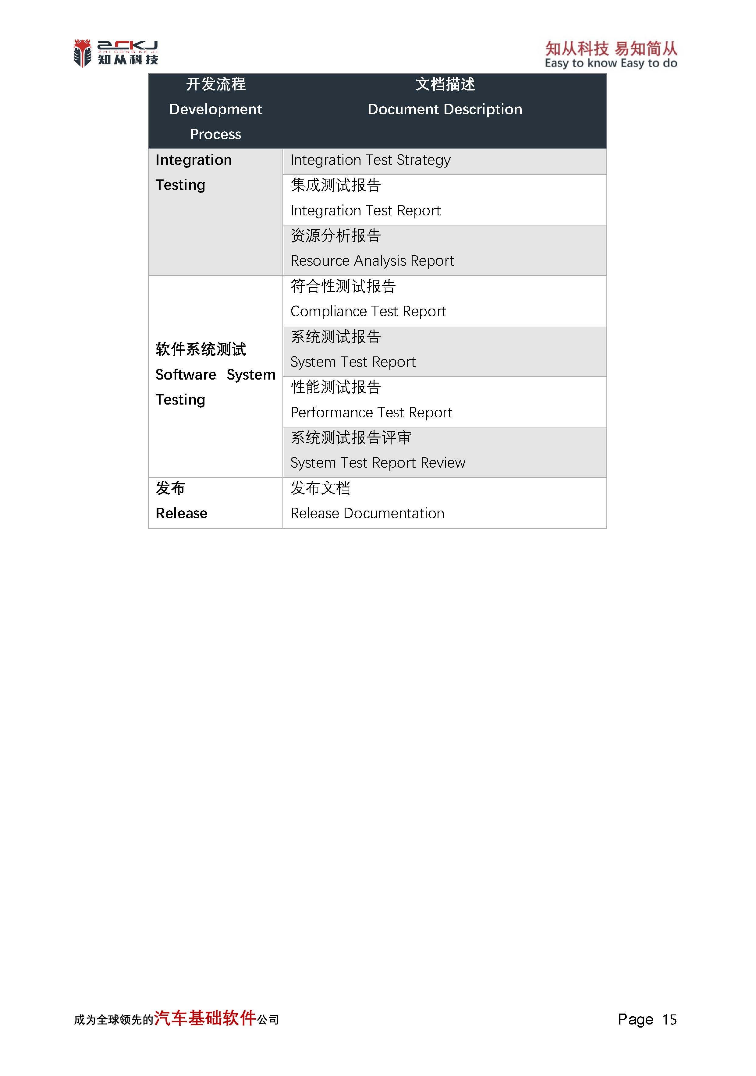
6 过程文档PROCESS DOCUMENTATION
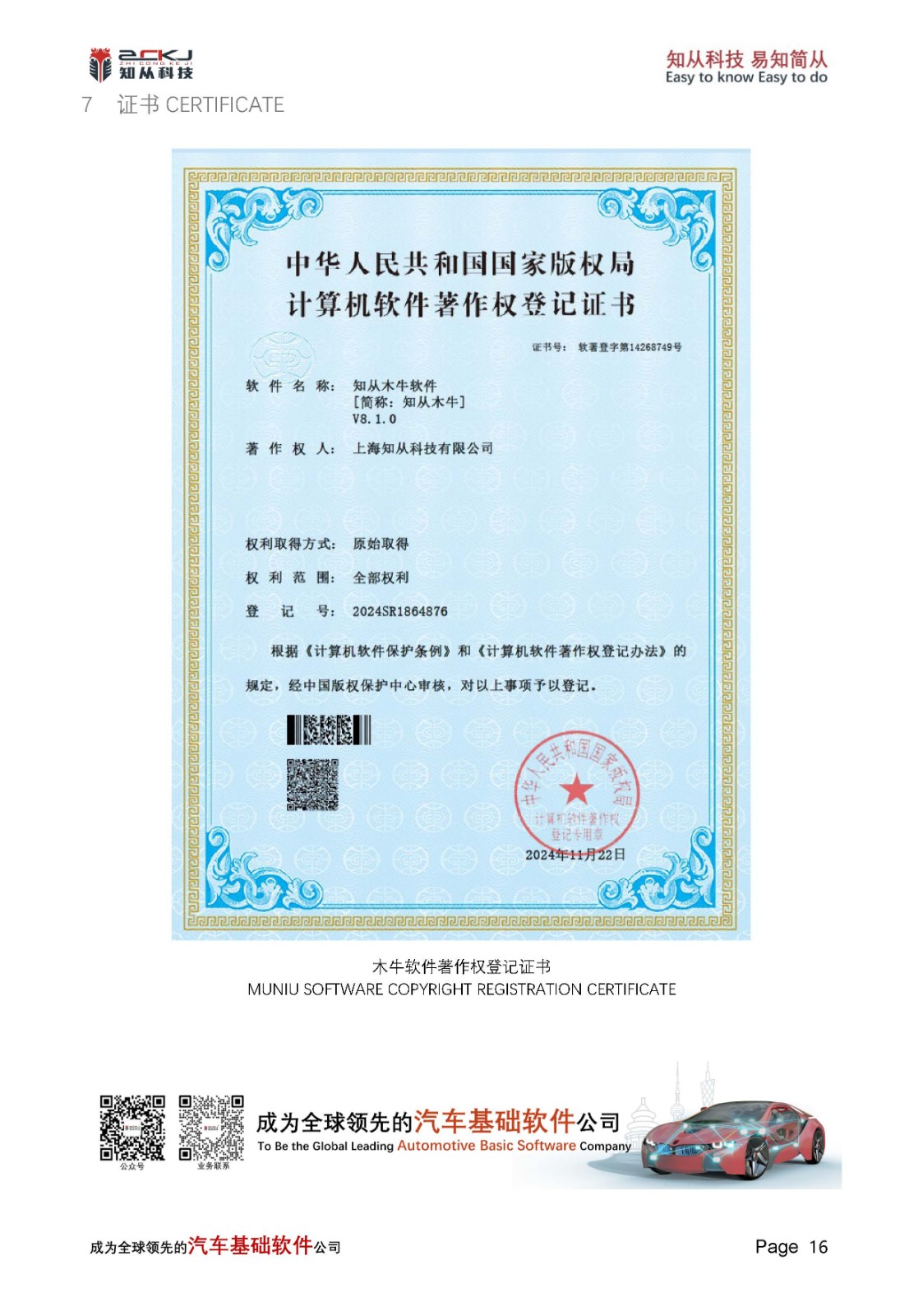
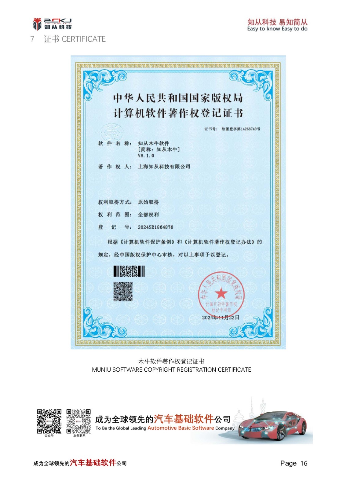
7 证书CERTIFICATE
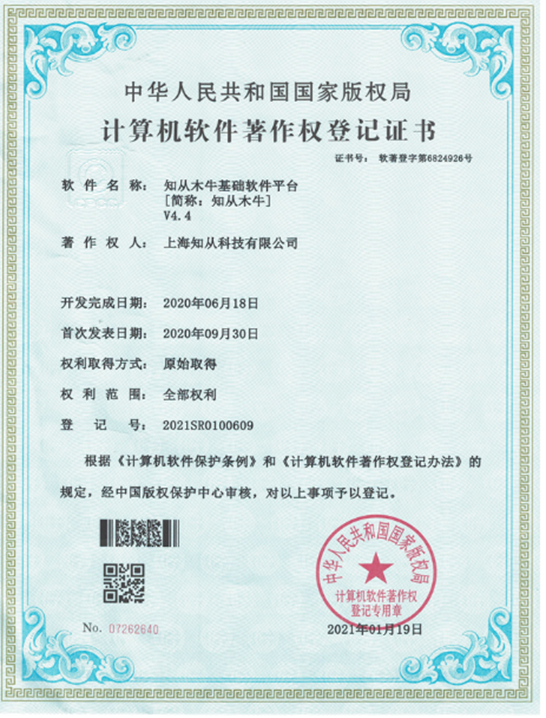
木牛软件著作权登记证书
MUNIU SOFTWARE COPYRIGHT REGISTRATION CERTIFICATE

收起


收起

收起