1 概述
在软件定义汽车(SDV)的浪潮下,汽车逐渐从“纯机械怪兽”演变为“移动的智能终端”。在这场变革中,底层软件的稳定性直接决定了上层应用的可靠性。作为汽车电子软件架构的中流砥柱,AUTOSAR 诊断协议栈(DiagnosticStack, 简称 DiagStack) 负责处理从物理层链路到Dcm诊断层的所有诊断数据交换。无论是下线检测(EOL)、售后维修,还是行车过程中的故障自检与安全降级,诊断栈都扮演着不可替代的角色。
2 DCM介绍
DCM 是诊断栈的对外窗口,负责处理外部诊断仪(Tester)与 ECU 之间的诊断通信。它直接对接 UDS (ISO 14229) 和 OBD (ISO 15031 / SAE J1979) 协议。在 AUTOSAR 规范中,DCM 被严谨地拆分为三个子层:DSL、DSD 和 DSP。
1、DSL (Diagnostic Session Layer - 诊断会话层)
DSL 负责管理整个诊断通信的状态机,处理会话(Session)切换和定时器(Timers):
会话状态管理: 管理 Default Session(默认会话)、Programming Session(编程会话) 以及 Extended Session(扩展会话) 之间的跳转。控制在未收到诊断请求时,经过 S3Server 超时后自动回退到默认会话的逻辑。
通信定时参数控制: 严格控制 UDS 协议中定义的 P2 和 P2* 时间。
P2 Server:ECU 收到请求后,必须在此时间内给出响应。
P2 Server*:如果 ECU 无法在 P2 时间内完成处理(例如正在写入 Flash),DSL 必须向诊断仪发送0x7F 0x78(Pending,否定响应码 NRC 78),并启动 P2* 定时器,争取更多的处理时间。
安全访问等级(Security Access): 管理解锁状态(Lock/Unlock)。配合 0x27 服务,DSL 会跟踪当前的 Security Level,确保只有通过密钥校验的诊断仪才能访问敏感数据或执行敏感例程。
2、DSD (Diagnostic Service Dispatcher - 诊断服务分发层)
DSD 处于承上启下的位置,主要负责对接收到的诊断请求(I-PDU)进行有效性校验,并将其准确分发:
服务 ID(SID)检查: 验证诊断仪发送的请求是否是当前架构支持的 UDS 服务。
权限仲裁: 检查请求的 SID 是否被允许在当前会话和当前安全等级下执行。例如,在 Default 状态下请求 0x2E(写 DID)或 0x31(例程控制),DSD会直接拒绝并返回对应的 NRC(Negative Response Code)。
格式与长度校验: 验证诊断报文的有效数据长度(Payload)是否符合该服务的规范。
3、DSP (Diagnostic Service Processing - 诊断服务处理层)
DSP 是具体业务逻辑的执行者。当 DSD 将合法的请求分发下来后,DSP 会解析具体的子服务(Sub-function)或数据标识符(DID),并调用底层的 SW-C(应用层软件)或 BSW 接口:
典型服务支持:
0x10 (DiagnosticSessionControl): 切换诊断会话。
0x22 / 0x2E (Read/Write DataByIdentifier): 读写标定参数或传感器数据(DID)。
0x19 (ReadDTCInformation): 从 DEM 获取当前的故障码信息。
0x14 (ClearDiagnosticInformation): 请求 DEM 清除故障内存。
0x31 (RoutineControl): 启动、停止或查询 ECU 内部的特殊测试例程(如传感器校准、执行器动作测试)。
0x34 / 0x36 / 0x37 (Request Download/Transfer Data/Exit): 在 Bootloader 刷写流程中,用于请求下载数据、传输数据切片和退出传输。
3 DEM介绍
DEM 是诊断栈的“中央数据库”,负责处理、记录和存储所有由 SW-C 或 BSW 模块上报的故障事件(Events)。它不仅仅是记录一个代码,而是维护一个庞大的故障状态机。
故障事件(Event)与 DTC 的映射
在 DEM 中,应用层上报的是 Event(事件),而对外(如 0x19 服务)呈现的是 DTC(Diagnostic Trouble Code)。
多个 Event 可以映射到同一个 DTC,或者一个 Event 对应一个独立的 DTC。
DEM 负责将具体的故障现象转换为符合 SAE J2012 或 ISO 15031-6 标准的 3 字节或 4 字节 DTC。
严苛的防抖(Debounce)机制
物理信号的抖动极易造成误报,DEM 提供了标准的防抖算法来过滤毛刺:
Counter-Based(基于计数器的防抖): 每次检测到 Fail,计数器加 StepUp值;检测到 Pass,计数器减 StepDown 值。当计数器超过 JumpUp 阈值时,故障才被标记为 Pre-Failed;超过 Failed 阈值时,故障被确认为 Failed。
Time-Based(基于时间的防抖): 故障必须持续指定的时间长度(如 200ms),DEM才会确认该故障。
DTC 状态掩码(Status Mask)的精密流转
DEM 严格遵循 ISO 14229-1 标准,为每个 DTC 维护一个 8 位的状态字节(Status Byte)。这是 DEM 最核心的技术细节:
Bit 0 (TestFailed): 当前测试周期内,最后一次测试结果为失败。
Bit 1 (TestFailedThisOperationCycle): 当前操作周期(Operation Cycle)内,曾经发生过失败。
Bit 2 (PendingDTC): 故障已经初步发生,处于待定状态。
Bit 3 (ConfirmedDTC): 故障经过防抖和多次周期验证,被正式确认,将写入 NVRAM(非易失性存储)。
Bit 4 (TestNotCompletedSinceLastClear): 自上次清除故障码以来,该测试尚未完成。
Bit 5 (TestFailedSinceLastClear): 自上次清除故障码以来,该测试曾经失败过。
Bit 6 (TestNotCompletedThisOperationCycle): 当前操作周期内,该测试尚未完成。
Bit 7 (WarningIndicatorRequested): 该故障触发了仪表盘报警灯(MIL灯)的请求。
冻结帧(Freeze Frame)与扩展数据(EDR)
当 Bit 3 (ConfirmedDTC) 被置 1 的瞬间,DEM 会执行“现场抓拍”:
Freeze Frame (0x02): 抓取发生故障瞬间的车辆关键上下文数据(如车速、发动机转速、电池电压、水温等),严格按照 DID 的形式打包存储。
Extended Data Record (0x06): 记录故障发生的次数(Fault Counter)、连续未发生故障的周期数(Aging Counter)等统计数据。
故障老化(Fault Aging)与覆盖(Displacement)
Aging: 当一个故障在连续 N 个操作周期内都不再复现(测试结果持续为 Pass),DEM 会将其从 NVRAM 中清除,释放存储空间。
Displacement: 如果 NVRAM 空间已满,新发生的严重故障(如 ASIL D 级安全故障)会根据优先级(Priority),覆盖并替换掉那些不重要的、低优先级的历史故障码。
4 FIM介绍
FIM 是 DEM 与应用层 SW-C 之间的桥梁,专门用于处理故障后的整车策略响应和安全降级(Fail-Safe)。
什么是功能抑制?
当 DEM 确定某个部件损坏(例如电子节气门传感器故障)后,FIM 需要立即采取行动,禁止依赖该传感器的某些高级功能(如定速巡航、自动驾驶辅助),以防止系统发生误动作导致安全事故。
FID(Function Inhibition Identifier)
在 FIM 中,每一个可以被独立禁止的应用层功能或算法模块,都会被分配一个唯一的标识符,称为 FID。
例如:FID_CruiseControl(定速巡航功能)、FID_ABS_Control(防抱死控制功能)。
抑制矩阵(Inhibition Matrix)
FIM 的核心是一张静态或动态配置的映射表(Matrix)。它定义了 DEM 的Event(事件)与 FIM 的 FID(功能标识)之间的对应关系。
示例关系: 当 Event_WheelSpeedSensor_Error(轮速传感器故障)的 DEM 状态满足特定条件(如 Confirmed 位被置 1)时,抑制矩阵会指示 FIM 激活对FID_ABS_Control 的抑制。
FIM 与 SW-C 的交互机制
应用层软件组件(SW-C)在执行核心控制逻辑之前,必须主动向 FIM 申请权限。常见的交互方式有两种:
轮询模式(Polling):SW-C 通过 RTE 调用 FIM 的 API(如 FiM_GetFunctionPermission),传入自己的 FID,询问“我当前是否被允许运行?”。
通知模式(Notification): 当抑制矩阵的状态发生改变时,FIM 主动通过 RTE 将最新的FID 状态推送给对应的 SW-C。
通过这种解耦设计,应用层开发者在编写具体的控制算法时,不需要关心底层是哪个传感器坏了,只需要向 FIM 询问当前功能是否可用,从而极大地提高了软件的模块化程度。
5 知从木牛CAN诊断协议栈
理论的严谨性最终需依托强大的工程平台方能转化为量产价值。针对智能汽车对底层软件日益增长的需求,知从木牛基础软件平台可以帮助OEM和Tier1更加快速的实现控制器开发。
作为一款立足于正向研发的BSW 产品,知从木牛基础软件平台在诊断与通信领域具备显著的技术优势:
前瞻性技术标准: 平台原生支持并满足 AUTOSAR R25-11 最新版本的规范要求,为客户提供具备高度前瞻性的控制器软件架构方案。
最高等级安全准则: 研发全流程深度契合 ISO 26262 功能安全标准,完全满足最高 ASIL D 级别的开发要求。从底层驱动到复杂的诊断事件管理,我们通过严谨的验证体系确保每一行代码的安全性。
高效本土化技术支持: 依托经验丰富的核心研发团队,知从科技致力于提供极速响应的本土化支持。无论是复杂的诊断策略配置,还是 CanTp 链路的深度调优,我们均能提供保姆式的工程咨询与定制服务,协助客户大幅缩短项目 SOP 周期。
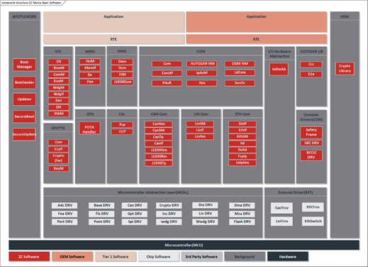
基础软件架构
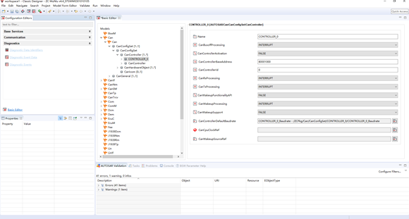
木牛配置工具主界面
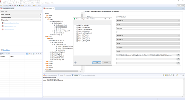
木牛配置工具生成配置代码
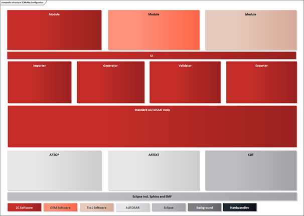
木牛配置工具架构
为了满足客户的不同项目需求,提高基础软件平台的扩展性, 木牛基础软件平台实现了各个模块可配置性,并且实现了配置工具。客户可根据不同需求,在配置工具上完成各个模块的配置工作,可生成配置代码文件,将生成的配置文件集成到工程中即可。
木牛基础软件平台的配置工具是基于Eclipse平台,并基于ARTOP架构,实现AUTOSAR模型和ARXML的解析。除了AUTOSAR标准定义的模块之外,还支持OEM和Tie1厂商二次开发自己的模块。配置完成后,可生成各个模块的配置代码。
Amidst the wave of Software-Defined Vehicles (SDVs), automobiles are gradually evolving from "purely mechanical beasts" into "mobile intelligent terminals." In this transformation, the stability of the underlying software directly determines the reliability of the upper-layer applications. As a cornerstone of automotive electronics software architecture, the AUTOSAR Diagnostic Stack (DiagStack) is responsible for handling all diagnostic data exchange—ranging from the physical layer link up to the Diagnostic Communication Manager (DCM) layer. Whether for End-of-Line (EOL) testing, after-sales maintenance, or in-vehicle fault self-diagnostics and safety degradation during operation, the Diagnostic Stack plays an indispensable role.
2 Introduction to DCM
DCM serves as the external interface of the diagnostic stack, responsible for managing diagnostic communication between an external diagnostic tool (Tester) and the ECU. It interfaces directly with the UDS (ISO 14229) and OBD (ISO 15031 / SAE J1979) protocols. Within the AUTOSAR specification, the DCM is rigorously partitioned into three distinct sub-layers: DSL, DSD, and DSP.
1. DSL (Diagnostic Session Layer)
The DSL is responsible for managing the state machine governing the entire diagnostic communication process, handling session transitions and timers:
Session State Management: Manages transitions between the Default Session, Programming Session, and Extended Session. It controls the logic for automatically reverting to the Default Session—specifically after the S3Server timeout expires—should no diagnostic requests be received.
Communication Timing Parameter Control: Strictly controls the P2 and P2* timing parameters defined within the UDS protocol.
P2 Server: The ECU must provide a response within this specified timeframe after receiving a request.
P2 Server*: If the ECU is unable to complete processing within the P2 timeframe (e.g., while writing to Flash memory), the DSL must send a 0x7F 0x78 response (indicating "Pending"—Negative Response Code NRC 78) to the diagnostic tool, thereby initiating the P2* timer to secure additional processing time.
Security Access Levels: Manages the lock/unlock status. In conjunction with Service 0x27, the DSL tracks the current Security Level, ensuring that only diagnostic tools that have successfully passed key validation can access sensitive data or execute sensitive routines.
2. DSD (Diagnostic Service Dispatcher)
The DSD occupies a pivotal position within the architecture; its primary responsibility is to validate the integrity of incoming diagnostic requests (I-PDUs) and accurately dispatch them to the appropriate handlers:
Service ID (SID) Check: Verifies whether the request sent by the diagnostic tool corresponds to a UDS service currently supported by the system architecture.
Authorization Arbitration: Checks whether the requested SID is permitted to be executed within the context of the current diagnostic session and the current security access level. For example, if a request for 0x2E (Write DID) or 0x31 (Routine Control) is received while in the Default state, the DSD will immediately reject it and return the corresponding NRC (Negative Response Code).
Format and Length Validation: Verifies whether the effective data length (Payload) of the diagnostic message complies with the specifications for the requested service.
3. DSP (Diagnostic Service Processing)
The DSP is the executor of the specific business logic. Once the DSD has dispatched a valid request, the DSP parses the specific Sub-function or Data Identifier (DID) and invokes the underlying SW-C (Application Layer Software) or BSW interfaces:
Typical Service Support:
0x10 (DiagnosticSessionControl): Switches the diagnostic session.
0x22 / 0x2E (Read/Write DataByIdentifier): Reads or writes calibration parameters or sensor data (DIDs).
0x19 (ReadDTCInformation): Retrieves current Diagnostic Trouble Code (DTC) information from the DEM.
0x14 (ClearDiagnosticInformation): Requests the DEM to clear the fault memory.
0x31 (RoutineControl): Starts, stops, or queries special internal test routines within the ECU (e.g., sensor calibration, actuator actuation tests).
0x34 / 0x36 / 0x37 (Request Download/Transfer Data/Exit): Used during the Bootloader flashing process to request data download, transfer data segments, and exit the transfer mode.
3 Introduction to DEM
The DEM serves as the "central database" of the diagnostic stack, responsible for processing, recording, and storing all fault events reported by SW-C or BSW modules. It does not merely record a simple code; rather, it maintains an extensive state machine for fault conditions.
1. Mapping of Fault Events to DTCs
Within the DEM, the Application Layer reports *Events*, whereas the interface exposed to external entities (e.g., via Service 0x19) presents *DTCs* (Diagnostic Trouble Codes).
Multiple Events may be mapped to a single DTC, or a single Event may correspond to a unique, standalone DTC.
The DEM is responsible for translating specific fault phenomena into 3-byte or 4-byte DTCs that comply with the SAE J2012 or ISO 15031-6 standards.
2. Robust Debouncing Mechanisms
Fluctuations in physical signals can easily lead to false positives; consequently, the DEM provides standard debouncing algorithms to filter out such transient spikes:
Counter-Based Debouncing: Each time a "Fail" condition is detected, a counter is incremented by a specified *StepUp* value; conversely, if a "Pass" condition is detected, the counter is decremented by a *StepDown* value. A fault is flagged as *Pre-Failed* only when the counter exceeds a specific *JumpUp* threshold; it is formally confirmed as *Failed* only when the counter surpasses the *Failed* threshold.
Time-Based Debouncing: A fault must persist for a specified duration (e.g., 200 ms) before the DEM formally confirms its existence.
3. Precise State Transitions for DTC Status Masks
The DEM strictly adheres to the ISO 14229-1 standard, maintaining an 8-bit *Status Byte* for each DTC. This constitutes the most critical technical detail within the DEM:
Bit 0 (TestFailed): The result of the most recent test execution within the current test cycle was a failure.
Bit 1 (TestFailedThisOperationCycle): A failure condition has occurred at least once during the current *Operation Cycle*.
Bit 2 (PendingDTC): The fault has preliminarily occurred and is currently in a pending state.
Bit 3 (ConfirmedDTC): The fault has undergone debouncing and verification across multiple cycles; it is now formally confirmed and will be written to NVRAM (Non-Volatile Random Access Memory).
Bit 4 (TestNotCompletedSinceLastClear): The specific diagnostic test associated with this DTC has not yet been completed since the last time the fault codes were cleared. Bit 5 (TestFailedSinceLastClear): This test has failed at least once since the last clearing of fault codes.
Bit 6 (TestNotCompletedThisOperationCycle): This test has not yet completed within the current operation cycle.
Bit 7 (WarningIndicatorRequested): This fault has triggered a request for the dashboard warning light (MIL) to illuminate.
4. Freeze Frame and Extended Data Record (EDR)
The moment Bit 3 (ConfirmedDTC) is set to 1, the DEM performs a "snapshot capture":
Freeze Frame (0x02): Captures key vehicle context data (such as vehicle speed, engine RPM, battery voltage, coolant temperature, etc.) at the exact instant the fault occurred, packaging and storing it strictly according to the DID format.
Extended Data Record (0x06): Records statistical data, such as the number of times the fault has occurred (Fault Counter) and the number of consecutive operation cycles during which the fault did not recur (Aging Counter).
5. Fault Aging and Displacement
Aging: If a fault does not recur for N consecutive operation cycles (i.e., the test result remains "Pass" continuously), the DEM will clear it from NVRAM, thereby releasing storage space.
Displacement: If the NVRAM storage space is full, a newly occurring severe fault (e.g., an ASIL D-level safety-critical fault) will—based on its Priority—overwrite and replace less critical, lower-priority historical fault codes.
4 Introduction to FIM
FIM serves as the bridge between the DEM and the Application Layer SW-Cs, specifically designed to manage vehicle-level strategic responses and safety degradation (Fail-Safe) measures following a fault.
What is Function Inhibition?
When the DEM identifies a component failure (e.g., an electronic throttle sensor fault), the FIM must take immediate action to inhibit certain advanced functions that rely on that sensor (such as cruise control or automated driving assistance systems). This prevents system malfunctions that could potentially lead to safety incidents.
FID (Function Inhibition Identifier)
Within the FIM, every application-layer function or algorithm module capable of being independently inhibited is assigned a unique identifier, known as an FID.
Examples: FID_CruiseControl (Cruise Control Function), FID_ABS_Control (Anti-lock Braking System Control Function).
Inhibition Matrix
At the core of the FIM lies a statically or dynamically configured mapping table (Matrix). This matrix defines the correspondence between DEM Events and FIM FIDs.
Example Relationship: When the DEM status for a specific event—such as Event_WheelSpeedSensor_Error (Wheel Speed Sensor Fault)—meets certain criteria (e.g., the "Confirmed" bit is set to 1), the Inhibition Matrix instructs the FIM to activate the inhibition of the FID_ABS_Control function.
Interaction Mechanism between FIM and SW-Cs
Before executing their core control logic, Application Layer Software Components (SW-Cs) must actively request permission from the FIM. There are two common interaction methods:
Polling Mode: The SW-C invokes a specific FIM API (e.g., `FiM_GetFunctionPermission`) via the RTE, passing its own FID to query: "Am I currently permitted to execute?"
Notification Mode: Whenever the state of the Inhibition Matrix changes, the FIM proactively pushes the latest status of the relevant FID to the corresponding SW-C via the RTE.
Through this decoupled design, application-layer developers—when writing specific control algorithms—do not need to concern themselves with which underlying sensor has failed; they simply need to query the FIM to determine whether the current function is available. This approach significantly enhances the modularity of the software.
5 ZC.MuNiu CAN DIAGNOSTIC PROTOCOL STACK
The rigor of theoretical concepts must ultimately be underpinned by a robust engineering platform to be successfully translated into value for mass production. Addressing the growing demand for foundational software in intelligent vehicles, the Zhicong Muniu foundational software platform empowers OEMs and Tier 1 suppliers to accelerate the development of control units.
As a BSW product built upon a foundation of forward engineering, the Zhicong MuNiu Basic Software Platform demonstrates significant technical advantages in the domains of diagnostics and communication:
Forward-Looking Technical Standards: The platform offers native support for—and complies with—the specifications of the latest AUTOSAR R25-11 release, providing customers with a highly forward-looking software architecture solution for their controllers.
Highest-Level Safety Standards: The entire R&D lifecycle is deeply aligned with the ISO 26262 functional safety standard, fully meeting the development requirements for the highest safety integrity level, ASIL D. From low-level drivers to complex diagnostic event management, we employ a rigorous verification framework to ensure the safety and security of every single line of code.
Efficient Localized Technical Support: Backed by a highly experienced core R&D team, Zhicong Technology is committed to providing rapid-response, localized technical support. Whether the task involves configuring complex diagnostic strategies or performing in-depth optimization of CAN-TP links, we offer comprehensive, hands-on engineering consulting and customization services to help our customers significantly accelerate their project SOP (Start of Production) timelines.
Software Architecture

MUNIU CONFIGURATION TOOL MAIN INTERFACE
MUNIU CONFIGURATION TOOL GENERATES CONFIGURATION CODE
To meet the requirements of customer and enhance the extensibility of the basic software platform, ZC.MuNiu has implemented configurable modules and configuration tool. Customers can use the configuration tool to configthe modules according to their specific needs, generate configuration code files, and integrate these files into projects.
ZC.MuNiu basic software platform configuration tool is based on the Eclipse platform and is built on the ARTOP architecture, which implements the parsing of the AUTOSAR model and ARXML. In addition to the modules defined by the AUTOSAR standard, it also supports OEM and Tie1 manufacturers to develop their own modules for secondary development. After the configuration is completed, the configuration code for each module can be generated.