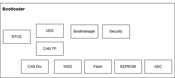
1 技术背景
传统 Bootloader 刷写中,数据下载(Download)与 Flash 编程(Program)多为严格串行:须等一整块数据经 CAN、以太网等总线完全接收并校验后,才能启动擦除与写入。高速总线等待 Flash 时空闲,Flash 等待下一块时空闲,形成“等待—忙碌”交替,资源利用率低,整体刷写时间被显著拉长。随着 ECU 程序存储从数百 KB 增至数 MB 甚至更大,该问题在产线下线与售后 OTA 中愈发突出。
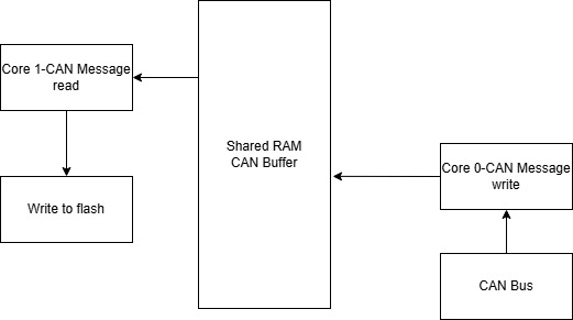
队列刷写引入 RAM 缓冲队列,将“接收块 N+1”与“编程块 N”在时间轴上重叠,以空间换时间。在 Flash 容量大或通信带宽相对有限时,收益最为明显。这是嵌入式 Bootloader 中经典的高效刷写策略。
知从青龙除pipeline外,还在诊断传输层增加多槽接收队列,以应对 UDS 连续多帧与 P2 应答约束;下文将二者统称为“两层队列”。
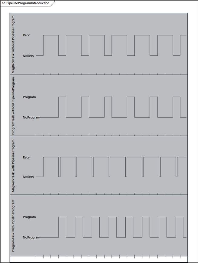
Figure 1 传统刷写和队列刷写时序对比
2 方案运行注意事项
知从科技可以为客户提供队列刷写方案,以下内容为方案实施的注意点:
l 队列停滞(并行度下降)
l 数据不同步(块错乱或校验失败)
当单块编程时间持续大于传输时间,缓冲槽位被占满,诊断仪只能等待,总时间接近串行,甚至伴随挂起增多或超时。除“生效前提与调参”外,应实测擦除段、传输段占用比,避免在编程峰值阶段仍采用最短发送间隔。
多缓冲切换时,若条件不严谨或缺少块序号核对,可能覆盖、错块编程,最终校验失败。设计上应保证:临界区保护、切换前多重状态检查、每块带序号且编程前核对。
3 常见问题剖析
在知从青龙队列刷写中,以下五类问题在联调、压力刷写与量产回归测试中反复出现。它们并不孤立:同一轮刷写中可能先后或叠加出现“响应超时”“仅主控失败”“从节点多包失败”等多种表现,若仅从单一报文或单一阶段判断,容易误判根因。
3.1 传输数据服务响应超时
刷写进行到一定进度后,诊断仪界面提示“响应超时”“未收到应答”或类似告警,进度条长时间停在某一百分比不动。此时上位机可能仍显示“正在发送数据”,给人以 ECU 仍在接收的错觉;若在 ECU 侧抓取日志或 CAN 记录,则往往能看到:对传输数据服务的请求已被确认,并反复回复“请求已正确接收—响应挂起”(行业惯称 NRC 0x78),但在较长时间内等不到该请求对应的最终正响应(传输数据服务的正常完成应答)。
从发生阶段看,该问题并非均匀分布在整个刷写过程中,而多集中在以下几类时刻:
l Flash 大面积擦除刚刚结束、即将开始或刚刚开始第一包数据传输时。擦除作业占用主循环时间极长,若擦除结束后未立即恢复对诊断链路的调度,首包传输数据极易撞上 P2 时限;
l 单包传输的数据长度明显大于常规块(例如接近单帧或多帧上限),导致单次入队、校验或后台预处理时间变长;
l 采用压缩格式下载时,后台解压占用主循环,且解压耗时随数据内容波动,某些区段出现“突发慢处理”;
l 诊断仪配置为较短的发送间隔或较高的并发期望,连续多帧传输数据之间的间隔小于 ECU 在“当前后台负载”下完成入队与首帧响应的能力。
CAN 上常见:连续传输数据请求 → 偶发挂起 → 长时间无响应 → 诊断仪判定 P2 超时并中止会话。
该问题经排查后,通常从以下方面处理
(1)区分“最后一块”与“中间块”的应答策略
对非最后一块:数据长度、块序号、地址范围等检查通过后,完成入队即应回复正响应,使诊断仪可以继续发送后续块;不得等待后台编程完成。对最后一块:须待数据队列排空、后台编程作业空闲后,再给出该块的最终正响应——这是正确性要求,现场不应将“最后一块晚应答”误判为本节的超时缺陷。
(2)建立“下一帧已就绪则主动挂起”的机制
当检测到通信队列中已有下一帧传输数据(或同类长耗时服务)待处理,且当前诊断发送通道空闲、尚未对上一请求给出最终响应时,应主动发送挂起响应,争取在 P2 内给出“首个响应”。该机制与“仅依赖周期任务轮询挂起”相比,可显著降低边界超时概率,尤其在擦除刚结束、首包紧接着到达的场景。
3.2 多从节点或主从联合刷写时会话超时
随着域控、区域控制器等架构普及,一次 OTA 或产线刷写往往需按顺序对多个对象完成固件更新:例如先主控、再从节点 A、再从节点 B;或两个从节点依次升级。队列刷写引入后,单个对象的传输数据阶段通常明显加快,但现场仍频繁报告:第一个对象全程正常,切换至第二个对象后出现问题。
分析发现,队列提高单对象吞吐,多对象仍受会话定时与互斥约束;队列刷写解决的是单对象时间轴上“接收与编程重叠”的效率问题,并未自动解决多对象时间轴上的会话保活、资源互斥与状态切换。
该问题经排查后,通常采用以下方案进行处理
(1)对象切换前的“排空 + 复位状态”*
每一对象刷写结束前,确认:数据队列无未处理块、通信队列无未递交帧、后台编程作业空闲、无未完成的挂起等待。再进入下一对象前,按项目规范重启或刷新 S3 等相关定时器,必要时执行会话保持交互。
(2)长作业周期挂起与 CAN 调度
对象 A 的擦除、大块转发等阶段,周期回复挂起并调度链路层,使诊断仪与会话保持逻辑认为 ECU 仍在响应。避免数秒级“完全无诊断报文”窗口。
(3)操作与“当前目标对象”绑定
复位、进入编程会话、保持会话、切换波特率等操作,应带目标对象判断,仅影响当前刷写节点。禁止在“即将刷 B”前对 B 或共用总线上的节点执行无关复位。
(4)区分验签失败与会话超时
验签失败时,先查失败前是否有 S3 超时、是否仍能正常响应会话保持或切换会话;若会话已失效,优先修复定时与切换流程,再重试验签。
3.3 开启队列刷写后,仅刷主节点亦失败
分析发现,从节点刷写场景中,主控除接收 CAN 诊断数据外,还需经 UART 或其它链路向从节点转发。转发往返时间往往远大于 CAN 上单块传输时间。为避免“主控已收块 N、从节点尚在写块 N−1”时诊断仪发送块 N+1 导致 P2 超时,软件常在发出一块数据后,暂时停止后台刷写主控任务,直到确认下一帧诊断数据已进入通信队列,再恢复后台并可能对队首请求回复挂起。
该问题经排查后,通常采用以下方案进行处理
(1)在途诊断帧计数的严格配对
从通信层分配接收缓冲开始计数,到诊断层取走数据或接收失败回滚时减计数。任何超时、BusOff 恢复、会话切换后应检查计数是否归零,防止泄漏。
(2)“等待下一帧”分支增加时间窗口
在暂停后台刷写的状态下启动定时;窗口内若检测到新帧进入通信队列,按从节点策略恢复;窗口到期仍无新帧,则判定为普通刷写,强制恢复后台任务与队列消费,清除“等待”状态。
(3)刷写模式配置分层
产品配置应明确区分:仅主控、仅某一从节点、主从联合等,避免用单一全局变量贯穿所有刷写路径。文档与标定数据应说明各模式适用场景。
4 知从青龙产品
知从青龙BootLoader是由知从科技自主研发的程序刷新软件(BootLoader)。使用知从青龙BootLoader的控制器,可以通过CAN、LIN、SPI等通信方式实现应用程序的更新功能。目前,知从青龙BootLoader已支持NXP、Infineon、Renesas、ST等多家芯片,并且支持多家整车厂程序刷新规范,可提供定制开发服务。
通常每家整车厂都有各自的程序刷新规范,目前知从青龙BootLoader支持的整车厂程序刷新规范包括:广汽、长安、上汽、一汽、东风商用车、东风、上海通用、吉利、奇瑞、上汽通用五菱、萨博、长城、北汽新能源等(以上排名不分先后)。
1 Technical Background
In conventional Bootloader flashing, data download and Flash programming are predominantly executed in a strictly sequential manner: the system must wait until an entire data block has been fully received and verified via CAN, Ethernet, or other vehicle buses before initiating the erase and write operations. During this process, the high-speed bus remains idle while waiting for the Flash to complete programming, and conversely, the Flash sits idle while awaiting the next data block. This alternating "wait–busy" pattern results in poor resource utilization and significantly prolongs the overall flashing time. As ECU program memory has grown from hundreds of kilobytes to several megabytes or even larger, this issue has become increasingly pronounced in both production-line end-of-line (EOL) programming and after-sales OTA updates.
Queue flashing introduces a RAM-based buffer queue to overlap the reception of block N+1 with the programming of block N in the time domain, trading memory space for reduced time. The benefits are most pronounced when Flash capacity is large or when communication bandwidth is relatively constrained. This is a classic high-efficiency flashing strategy in embedded Bootloaders.
In addition to data-layer ping-pong buffering, ZC.QingLong implements a multi-slot reception queue at the diagnostic transport layer to address UDS consecutive multi-frame transmission and P2 response timing constraints. For the purposes of this discussion, both mechanisms are collectively referred to as the "two-layer queue."
FIGURE 1 Timing Diagram: Traditional Flashing vs. Queue Flashing
2 Implementation Considerations
ZhiCong Technology can provide customers with the queue flashing solution. The following points require attention during implementation:
Queue Stall (Parallelism Degradation)
Data Desynchronization (Block Misalignment or Verification Failure)
When the programming time of a single block persistently exceeds the transmission time, the buffer slots become fully occupied, forcing the diagnostic tester to wait. The total time then approaches that of sequential flashing, potentially accompanied by an increased number of suspensions or timeouts. Beyond verifying the activation prerequisites and tuning parameters, the actual erase-segment and transmission-segment occupancy ratios should be measured. Avoid using the shortest transmission interval during peak programming phases.
During multi-buffer switching, if the conditions are not rigorously enforced or block sequence number verification is omitted, overwrites or incorrect block programming may occur, ultimately resulting in verification failure. The design must guarantee: critical section protection, multiple state checks prior to buffer switching, and inclusion of a sequence number with each block that is verified before programming.
3 Common Issue Analysis
In the ZC QINGLONG queue flashing process, the following five categories of issues recur during integration debugging, stress flashing, and mass-production regression testing. They are not isolated: within a single flashing session, multiple symptoms such as "response timeout," "master node failure only," and "multi-packet failure on slave nodes" may appear sequentially or simultaneously. If diagnosis is based solely on a single message or a single phase, the root cause is prone to misjudgment.
3.1 TransferData Service Response Timeout
After the flashing process reaches a certain progress, the diagnostic tool interface displays warnings such as "Response Timeout" or "No Response Received," and the progress bar remains stuck at a certain percentage for an extended period. At this time, the host computer may still display "Sending Data," creating the illusion that the ECU is still receiving. However, if logs or CAN traces are captured on the ECU side, it is often observed that: the request for the TransferData service has been acknowledged, and the ECU repeatedly replies with "Request Sequence Error - Response Pending" (commonly referred to in the industry as NRC 0x78), yet the final positive response corresponding to that request (the normal completion acknowledgment for the TransferData service) fails to arrive within a considerable time frame.
From the perspective of the occurrence phase, this issue is not uniformly distributed throughout the flashing process; it predominantly concentrates at the following moments:
l Immediately before, during, or right after Flash mass erase: The erase operation occupies the main loop for an extremely long duration. If diagnostic link scheduling is not resumed immediately after the erase completes, the first data transfer packet is highly likely to breach the P2 timeout.
l Single-packet data length significantly exceeds the standard block size (e.g., approaching the Single Frame or Multi-Frame length limit), resulting in prolonged queuing, checksum verification, or background preprocessing time.
l Compressed format download: Background decompression consumes the main loop, and the processing time fluctuates with data content, leading to "sudden slow processing" in certain segments.
l Tester configured with aggressive timing: Short inter-frame transmission intervals or high concurrency expectations are set on the tester. The interval between consecutive multi-frame data transfers is shorter than the ECU's capability to complete queuing and the initial frame response under the current background load.
On the CAN bus, the typical symptom is: Continuous Transfer Data Request → Occasional Busy/Hang → Prolonged No Response → Tester judges P2 Timeout and aborts the session.
Root Cause Analysis & Countermeasures
After investigation, the issue is typically addressed through the following measures:
(1) Differentiating Response Strategy for "Last Block" vs. "Intermediate Blocks"
For non-last blocks: Upon passing checks (data length, block counter, address range, etc.) and completing queuing, a positive response must be sent immediately to allow the tester to proceed with subsequent blocks. Do not wait for the background programming operation to finish.
For the last block: The final positive response must be withheld until the data queue is drained and the background programming job is idle—this is a correctness requirement. On-site personnel should not misclassify "late response of the last block" as a timeout defect described in this section.
(2) Implementing a "Proactive Pending" Mechanism
When detecting that the next frame (or another long-duration service) is already queued for processing, and the current diagnostic transmit channel is idle while the final response to the previous request has not yet been issued, a Pending Response (0x78) should be actively sent to secure the "first response within P2." Compared to mechanisms relying solely on periodic task polling for pending status, this approach significantly reduces boundary timeout probabilities, especially in scenarios where the first packet arrives immediately after an erase operation ends.
3.2 Session Timeout During Multi-Slave or Master-Slave Combined Flashing
With the proliferation of domain controllers and zone controller architectures, a single OTA or production line flashing process often requires sequential firmware updates for multiple targets: for example, updating the Master Control Unit first, followed by Slave Node A, then Slave Node B; or upgrading two slave nodes sequentially. After introducing queued flashing, the data transfer phase for individual targets is usually significantly faster. However, field reports frequently indicate that the first target operates normally, but issues arise when switching to the second target.
Analysis reveals that while queuing improves single-target throughput, multi-target operations remain constrained by session timing and mutual exclusion. Queued flashing addresses the efficiency of "overlapping reception and programming" on a single object's timeline; it does not automatically resolve session keep-alive, resource contention, and state switching across multiple objects' timelines.
Root Cause Analysis & Countermeasures
After investigation, the following solutions are typically implemented:
(1) "Drain + Reset State" Before Target Switching*
Before concluding the flashing of each target, confirm that: the data queue contains no unprocessed blocks, the communication queue has no pending frames, the background programming job is idle, and there are no outstanding pending waits. Before proceeding to the next target, restart or refresh relevant timers (such as S3) according to project specifications, and perform session keep-alive interaction if necessary.
(2) Long Job Cycle Pending and CAN Scheduling
During phases involving Flash erase or large-block forwarding for Object A, periodically send Pending Responses (NRC 0x78) and schedule the link layer to ensure the tester and session management logic recognize the ECU as still responding. Avoid multi-second windows of "complete diagnostic silence."
(3) Binding Operations to the "Current Target Object"
Operations such as reset, entering the Programming Session, session keep-alive, and baud rate switching must include target object identification logic and affect only the currently active flashing node. It is prohibited to execute irrelevant resets on Node B or any nodes sharing the bus just before "flashing B is about to start."
(4) Differentiating Signature Verification Failure from Session Timeout
Upon signature verification failure, first check whether an S3 timeout occurred prior to the failure and whether the ECU can still respond normally to session keep-alive or session switching requests. If the session has expired, prioritize fixing the timing and switching flow before retrying the signature verification.
3.3 Session Timeout During Multi-Slave or Master-Slave Combined Flashing
Analysis revealed that in a slave node flashing scenario, the Master Control Unit must forward data to slave nodes via UART or other links, in addition to receiving CAN diagnostic data. The round-trip forwarding time is often significantly longer than the CAN single-block transfer time. To prevent the tester from sending Block N+1 and causing a P2 timeout while the "Master has received Block N but the Slave is still writing Block N-1," the software often temporarily suspends the background Master flashing task after transmitting one block. It resumes the background task only upon confirmation that the next diagnostic frame has entered the communication queue, potentially issuing a Pending Response for the head-of-queue request.
Root Cause Analysis & Countermeasures
After investigation, the following solutions are typically implemented:
(1) Strict Pairing of In-Flight Diagnostic Frame Counters
Counting should begin when the communication layer allocates receive buffers and decrement when the diagnostic layer retrieves the data or when reception fails and rolls back. After any timeout, BusOff recovery, or session switching, verify that the counter has returned to zero to prevent leaks.
(2) Adding a Time Window to the "Wait for Next Frame" Branch
Start a timer when the background flashing task is suspended. If a new frame is detected entering the communication queue within the window, resume operation according to the slave node strategy. If the window expires and no new frame has arrived, classify the operation as a normal flash sequence, forcibly resume the background task and queue consumption, and clear the "waiting" state.
(3) Layered Configuration of Flashing Modes
Product configurations must explicitly distinguish between modes such as "Master Only," "Specific Slave Only," and "Master-Slave Combined," avoiding the use of a single global variable across all flashing paths. Documentation and calibration data should specify the applicable scenarios for each mode.
4 ZC.QingLong
ZC.QingLong BootLoader is a self-developed flash programming software (BootLoader) by ZCTechnology. Controllers using ZC.QingLong BootLoader can update the application through communication methods such as CAN, LIN, and SPI. Currently, ZC.QingLong BootLoader has supported multiple chips from manufacturers like NXP, Infineon, Renesas, and ST, and complies with the program refreshing specifications of various vehicle manufacturers. It also offers customized development services.
Typically, each vehicle manufacturer has its own specifications for program refreshing. The vehicle manufacturers whose program refreshing specifications are currently supported by ZC.QingLong BootLoader include: GAC (Guangzhou Automobile), Changan, SAIC (Shanghai Automotive Industry Corporation), FAW (First Automobile Works), Dongfeng Commercial Vehicles, Dongfeng, SGMW (SAIC General Motors Wuling), Geely, Chery, SAIC-GM-Wuling, Saab, Great Wall, BAIC New Energy, etc. (listed in no particular order).

 收起
收起