1 概述 Overview
玄武上位机软件用来将电子控制器中的应用程序和数据,从PC端下载到电子控制器上。支持UDSonCAN、UDSonEth、UDSonK-Line、UDSonLIN协议。提供客户协议定制集成,广泛应用在电子控制器产品开发阶段,测试阶段,售后服务阶段。
ZC.XuanWu upper computer software is used to download application programs and data from the PC to the electronic controller. It supports UDS on CAN, UDS on Eth, UDS on K-Line, and UDS on LIN protocols. It offers customized integration of customer-specific protocols and is widely used in the development, testing, and after-sales service stages of electronic controller products.
知从玄武程序刷新与诊断测试工具可应用于OEM和Tier1多种应用场景下。用户可以方便的在实验室,试验车辆以及实车上方便的进行程序刷写工作。
ZC.XuanWu program refresh and diagnostic testing tools can be applied in various application scenarios for OEMs and Tier 1 suppliers. Users can conveniently perform program flashing work in laboratories, test vehicles, and actual vehicles.
玄武上位机软件目前应用于各类电子控制器的程序刷写:
ZC.XuanWu upper computer software is currently used for program flashing of various electronic controllers:
Ø 车身控制器Body Control Module (BCM)
Ø 空调控制器Air Conditioning Controller
Ø DC/DC控制器DC/DC Converter
Ø 电子助力转向控制器Electric Power Steering Controller
Ø 发动机控制器Engine Management System (EMS)
Ø 变速箱控制器Transmission Control Module (TCM)
Ø 电池管理系统Battery Management System (BMS)
Ø 整车控制器Vehicle Control Unit (VCU)
Ø 电机控制器Motor Control Unit (MCU)
Ø 电动助力转向系统Electric Power Steering System (EPS)
Ø 防抱死制动系统Anti-lock Braking System (ABS)
Ø 电子稳定性控制程序Electronic Stability Program (ESP)
Ø 主动防撞系统Active Collision Avoidance System (ACC)
Ø 牵引力控制系统Traction Control System (TCS)
Ø ADAS控制器Advanced Driver Assistance Systems Controller
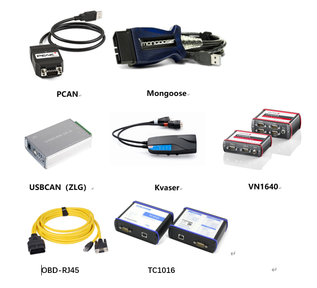
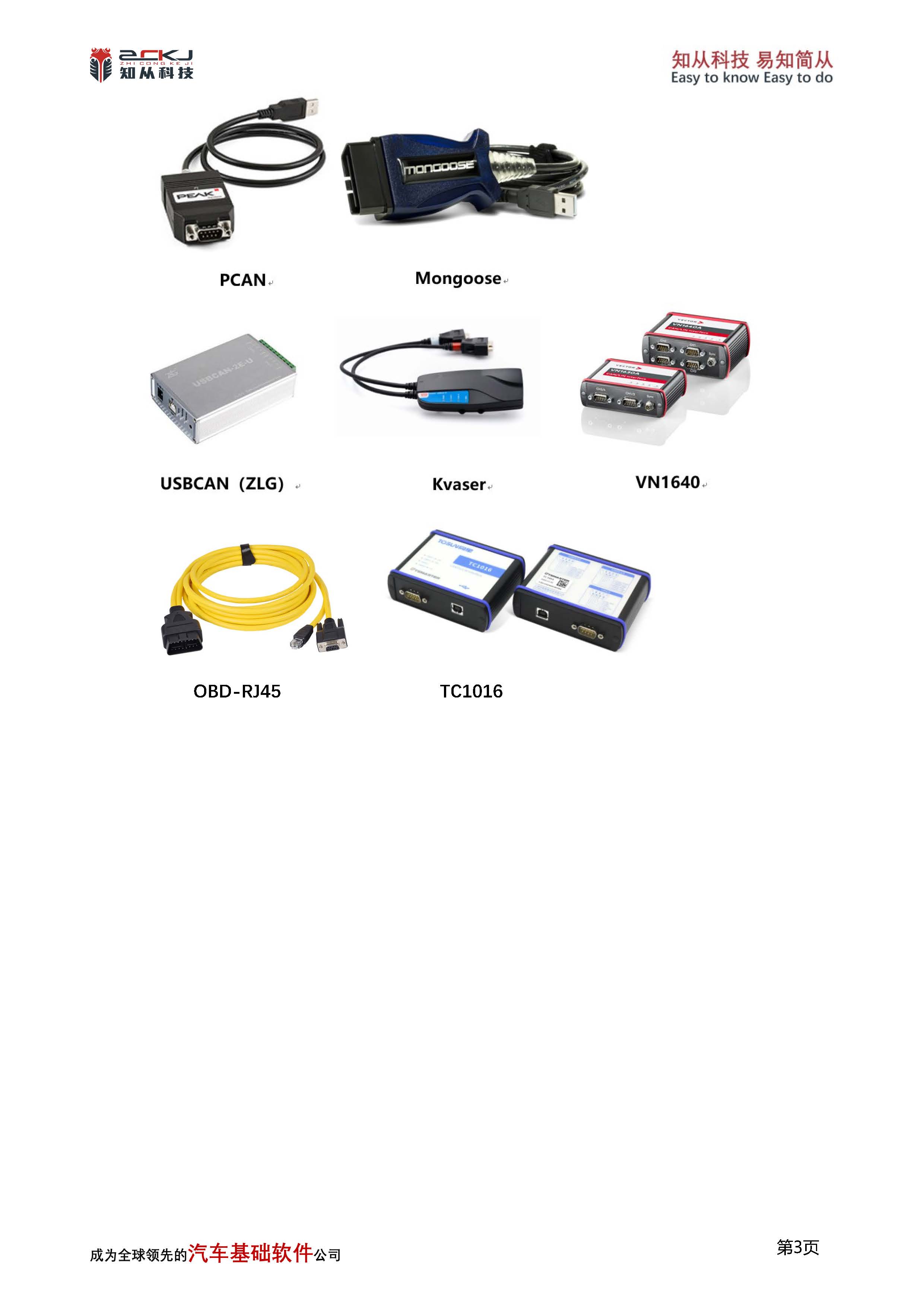
配置环境Configuration Environment | |
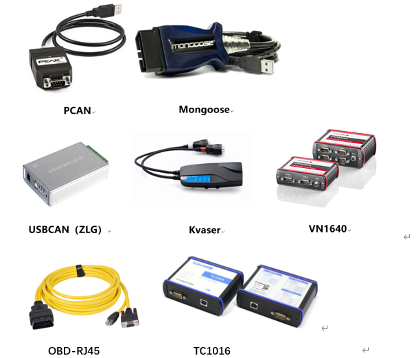
Hardware | PCAN、Mongoose、Kvaser、USBCAN(ZLG)、VN1640、TC1016、OBD-RJ45 |
Configuration Environment | Win7/10 64bit |
玄武上位机支持下述设备:
2 VBF文件介绍 VBF File Introduction
在智能网联汽车“软件定义车辆”的时代背景下,整车电子电气架构日趋集中化,ECU(电子控制单元)软件迭代频率从年级缩短至周级甚至天级。海量的固件升级任务通过 OTA(空中下载技术)下发至车辆,这对刷写过程的安全性、完整性及工程效率提出了前所未有的挑战。在此背景下,VBF(Versatile Binary Format,通用二进制格式)文件 成为确保安全、可靠、可管控的 ECU 刷写的关键数据载体。此外,在汽车信息安全与功能安全领域,VBF 文件与数字签名、加密技术形成了协同防护体系。通常采用 “先签名后加密” 或 “先计算哈希后传输” 的处理流程——即对原始固件生成数字签名并嵌入 VBF 结构,再对整体文件进行可选的加密传输。这种方式不仅能通过签名机制防止非法固件刷入,还能借助 VBF 内嵌的多级校验块(如 RootHash、CRC)在刷写前、传输中、写入后分别验证数据完整性,使中间人攻击、固件篡改和回滚攻击难以得逞。
Against the backdrop of the "software-defined vehicle" era in connected and autonomous electric vehicles, the overall vehicle E/E architecture is becoming increasingly centralized. The iteration frequency of ECU software has shortened from yearly to weekly or even daily cycles. Massive firmware upgrade tasks are delivered to vehicles via OTA (Over‑The‑Air) technology, posing unprecedented challenges to the security, integrity, and engineering efficiency of the flash programming process. In this context, the VBF (Versatile Binary Format) file has become a key data carrier for ensuring safe, reliable, and controllable ECU flashing. Furthermore, in the fields of automotive cybersecurity and functional safety, the VBF file forms a collaborative protection system together with digital signatures and encryption technologies. The typical processing flow follows a "sign‑then‑encrypt" or "hash‑then‑transmit" approach – i.e., generating a digital signature on the original firmware, embedding it into the VBF structure, and then optionally encrypting the entire file for transmission. This method not only prevents illegal firmware from being flashed through the signature mechanism, but also leverages the multi‑level verification blocks embedded in VBF (such as RootHash and CRC) to validate data integrity before flashing, during transmission, and after writing. As a result, man‑in‑the‑middle attacks, firmware tampering, and rollback attacks are rendered much more difficult.
VBF文件主要由三大部分组成:文件头(Header)、数据块(Data Blocks) 和 校验块(Verification Block)。文件头以ASCII文本形式存储目标ECU地址、擦除参数、版本号等刷写元数据;数据块承载实际的固件代码或校准数据,可分段存储并支持压缩算法;校验块则包含RootHash、双重数字签名及CRC校验值,用于在刷写前、传输中和写入后验证文件的完整性与真实性。
A VBF file mainly consists of three parts: Header, Data Blocks, and Verification Block. The Header stores flash programming metadata such as target ECU address, erase parameters, and version number in ASCII text format. The Data Blocks carry the actual firmware code or calibration data, which can be stored in segments and support compression algorithms. The Verification Block contains the RootHash, dual digital signatures, and CRC check values, used to verify the integrity and authenticity of the file before, during, and after the flash programming process.
2.1 VBF文件详细介绍 Detailed Introduction to the VBF File Structure
VBF(Versatile Binary Format,通用二进制格式)作为一种结构化混合格式文件,与HEX、S19等传统固件格式不同,VBF在单纯存放二进制数据的基础上,增加了丰富的元数据描述和多层级安全校验机制,是一个集配置指令、二进制固件、完整性校验和数字签名于一体的混合封装格式。
VBF (Versatile Binary Format) is a structured hybrid format file. Unlike traditional firmware formats such as HEX and S19, which simply store binary data, VBF adds rich metadata descriptions and multi‑level security verification mechanisms. It is a hybrid packaging format that integrates configuration instructions, binary firmware, integrity checks, and digital signatures.
从整体结构来看,VBF文件由三大核心部分组成:版本段、文件头段和数据段。在VBF 2.6及以上版本中,数据段内部还嵌套了VBT(校验块表) ,文件末尾还独立存在Verification Block(校验隔离区) ,后者存放着整包的安全总成——RootHash和双重数字签名。以下对每个部分进行详细介绍。
From an overall structural perspective, the VBF file consists of three core parts: the version segment, the header segment, and the data segment. In VBF version 2.6 and above, the data segment internally embeds a VBT (Verification Block Table), and at the end of the file there exists an independent Verification Block, which stores the entire package’s security assembly — the RootHash and the dual digital signatures. Each part is described in detail below.
文件头段(Header):
文件头段(Header)紧接在版本段之后,以ASCII文本形式存储,并用大括号包裹整个字段集合,是VBF文件中定义刷写流程元数据与配置指令的核心区域。该段包含了软件零件号(sw_part_number)、软件版本(sw_version)、软件包类型(sw_part_type)、ECU物理目标地址(ecu_address)、擦除区间列表(erase)、程序入口地址(call)、校验块表起始地址与长度(verification_block_start / length)、RootHash值(verification_block_root_hash)以及文件级CRC32校验和(file_checksum)等关键字段。Header段的作用是为解析工具和ECU提供刷写前必须的兼容性检查、地址映射、Flash擦除规划及安全校验定位信息,直接决定了固件能否被正确识别、加载并安全写入目标ECU。
The Header segment immediately follows the version segment. It is stored in ASCII text format, with the entire field set enclosed in curly braces. It serves as the core area within the VBF file that defines the flash programming metadata and configuration instructions. This segment contains key fields such as the software part number (sw_part_number), software version (sw_version), software part type (sw_part_type), ECU physical target address (ecu_address), erase area list (erase), program entry address (call), verification block table start address and length (verification_block_start / length), RootHash value (verification_block_root_hash), and file‑level CRC32 checksum (file_checksum). The role of the Header segment is to provide the parsing tool and the ECU with the necessary pre‑flash compatibility checks, address mapping, Flash erase planning, and security verification locating information. It directly determines whether the firmware can be correctly identified, loaded, and safely written to the target ECU.
数据段(Data Blocks):
数据段以纯二进制格式存储,是整个VBF文件中实际承载固件代码或标定数据的核心载体。该段由多个连续排列的数据块(Block)构成,每个Block均包含4字节起始地址、4字节数据长度、n字节有效二进制数据以及2字节CRC-16校验位。数据段的作用是为解析工具和ECU提供分段可寻址、可校验的刷写数据映像,支持将不同功能的代码或数据分散存放于Flash的不同地址区间,并在刷写过程中通过块级CRC校验保证每段数据传输的完整性
The Data Segment is stored in pure binary format and serves as the core carrier within the entire VBF file that actually holds the firmware code or calibration data. This segment consists of multiple consecutively arranged data blocks. Each block contains a 4‑byte start address, a 4‑byte data length, n bytes of valid binary data, and a 2‑byte CRC‑16 checksum. The role of the Data Segment is to provide the parsing tool and the ECU with a segmented, addressable, and verifiable flash programming data image. It supports the分散存放 (distribution) of code or data with different functions across different address ranges of the Flash memory, and ensures the integrity of each data block during the flash programming process through block‑level CRC verification.
校验块表(Verification Block Table):
VBT段并非独立于数据段的区域,而是数据段中一个具有特殊身份的数据块。该块内部存放的是数据段内除自身以外所有其他Block的哈希值列表(每个哈希值采用SHA-256算法计算),同时记录了各Block的起始地址与长度信息。VBT的核心作用是为数据段的整体完整性建立“集体指纹”——解析工具或ECU读取VBT后,对其整体(起始地址、长度、哈希表数据)再次进行SHA-256运算,得到RootHash,进而与文件头段中的verification_block_root_hash字段进行比对。通过这一设计,VBT将分散在各个数据块中的内容通过哈希链汇聚成一个可被数字签名保护的安全锚点,实现了从“单个Block校验”到“全数据段防篡改”的信任传递。
The VBT segment is not an area independent of the Data Segment; rather, it is a data block with a special identity within the Data Segment. Inside this block is stored a list of hash values (each hash calculated using the SHA‑256 algorithm) of all other blocks within the Data Segment except itself, along with the start address and length information of each block. The core function of the VBT is to establish a "collective fingerprint" for the overall integrity of the Data Segment – after the parsing tool or ECU reads the VBT, it performs a SHA‑256 operation on the entire VBT content (start address, length, hash table data) to obtain the RootHash, which is then compared with the verification_block_root_hash field in the Header segment. Through this design, the VBT aggregates the content distributed across individual data blocks via a hash chain into a single security anchor that can be protected by digital signatures, achieving a trust transfer from "single‑block verification" to "full Data Segment tamper‑proofing".
签名段(Verification Block):
签名段(Verification Block,校验块)位于VBF文件的末尾(VBF 2.6及以上规范),以二进制格式独立存放,是整个文件的安全总成与信任锚点。该段承载了两类核心安全数据:RootHash值与双重RSA-2048数字签名(研发签名 sw_signature_dev 和生产签名 sw_signature)。其作用是为ECU提供固件来源可信性与完整性的终极验证依据——ECU在执行刷写前,首先从签名段提取数字签名并使用内置公钥解密,得到理论上应匹配的RootHash;同时,从数据段中定位VBT,对其执行SHA-256哈希运算得出实际RootHash;将两者进行比对,若一致则证明固件自生成后未被篡改且来自合法持有私钥的签发方(Tier1或OEM)。通过将签名段置于文件末尾并与文件头段中的 verification_block_root_hash、verification_block_start/length 等字段形成交叉引用,VBF实现了从固件内容 → VBT → RootHash → 数字签名的全链路防篡改信任传递。
The Signature Segment (Verification Block) is located at the end of the VBF file (VBF version 2.6 and above), stored independently in binary format. It serves as the security assembly and trust anchor for the entire file. This segment carries two core types of security data: the RootHash value and dual RSA‑2048 digital signatures (the development signature sw_signature_dev and the production signature sw_signature). Its role is to provide the ECU with the ultimate verification basis for firmware source authenticity and integrity – before performing a flash programming operation, the ECU first extracts the digital signature from the Signature Segment and decrypts it using the built‑in public key, obtaining the theoretically expected RootHash. Simultaneously, it locates the VBT within the Data Segment and performs a SHA‑256 hash operation on it to derive the actual RootHash. The two are then compared; if they match, it proves that the firmware has not been tampered with since its generation and originates from a legitimate signer (Tier‑1 or OEM) holding the corresponding private key. By placing the Signature Segment at the end of the file and creating cross‑references with fields such as verification_block_root_hash, verification_block_start/length, etc., in the Header segment, VBF achieves a full‑chain tamper‑proof trust transfer from: firmware content → VBT → RootHash → digital signature.
3 玄武VBF文件下载功能介绍 Introduction to Xuanwu VBF File Download Function
3.1 VBF文件传输配置 VBF File Transfer Configuration
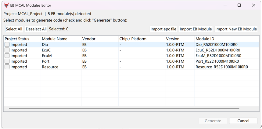
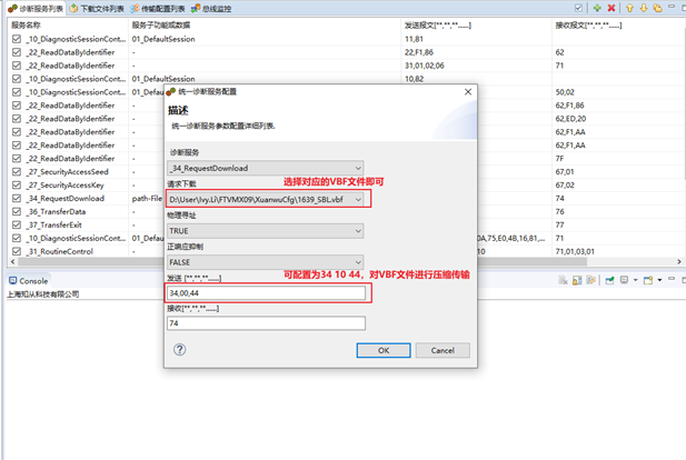
玄武支持用户向ECU发送单条或多条诊断报文,针对VBF文件刷写,玄武支持在新建UDS 0x34服务时进行配置,选择_34_RequestDownload,点击Path-File选择文件,并可配置为34 10 44,选择压缩传输或正常刷写
Xuanwu supports users in sending single or multiple diagnostic messages to the ECU. For VBF file flashing, Xuanwu allows configuration when creating a new UDS 0x34 service: select _34_RequestDownload, click Path‑File to choose the file, and configure it as 34 10 44, then select either compressed transmission or normal flashing.
玄武默认 dataFormatIdentifier为0x00,用户需要配置刷写文件起始地址、刷写文件Size。
Xuanwu defaults the dataFormatIdentifier to 0x00. The user needs to configure the start address of the flash file and the size of the flash file.
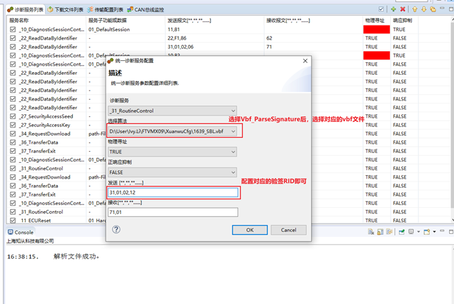
3.2 VBF文件签名传输配置 VBF File Signature Transfer Configuration
玄武支持用户向ECU发送VBF文件中的Signature,支持在新建UDS 0x31服务时进行配置,选择_31_RoutineControl,点击VBF-Signature选择文件,并配置31服务对应的RID即可,玄武会自动读取VBF文件中对应的签名,从而进行刷写过程中的验签操作。
Xuanwu supports users in sending the signature from a VBF file to the ECU. It allows configuration when creating a new UDS 0x31 service: select _31_RoutineControl, click VBF‑Signature to choose the file, and configure the RID corresponding to the 0x31 service. Xuanwu will then automatically read the corresponding signature from the VBF file to perform signature verification during the flashing process.
4 证书CERTIFICATE
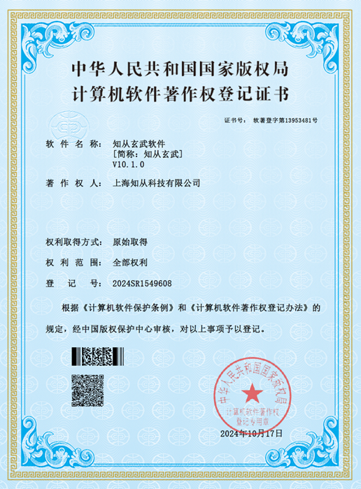
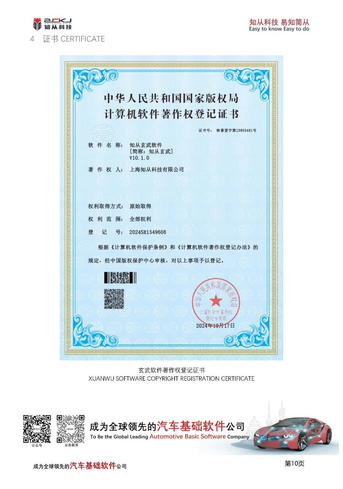
玄武软件著作权登记证书
XUANWU SOFTWARE COPYRIGHT REGISTRATION CERTIFICATE
 收起
收起
1 功能概述FUNCTIONAL OVERVIEW
知从玄武标定上位机工具是一种基于ASAM标准的通用测量与标定协议工具,支持多通信协议(如CAN、CANFD、Eth等),专为汽车电子控制单元(ECU)的在线标定、数据采集和调试设计。其核心功能包括:
实时数据采集:支持Polling(轮询)和DAQ(数据采集)两种模式。在线参数标定:动态调整ECU参数并实时生效,支持块标定、二维数组标定。Flash编程:将标定后的参数生成hex文件,可烧录存储至ECU的Flash中,确保持久化生效。多协议兼容:支持XCP-on-CAN、XCP-on-CANFD,XCP-on-Ethernet等多种传输层,适配不同车载网络环境。
The ZC.XuanWu Calibration Tool is a general-purpose measurement and calibration protocol tool based on ASAM standards, supporting multiple communication protocols (such as CAN, CANFD, Ethernet, etc.). It is specifically designed for online calibration, data collection, and debugging of automotive electronic control units (ECUs). Its core functions include:
Real-time Data Collection: Supports both Polling (cyclic query) and DAQ (data acquisition) modes.
Online Parameter Calibration: Dynamically adjusts ECU parameters that take effect in real-time, supporting block calibration and 2D array calibration.
Flash Programming: Generates hex files from calibrated parameters, which can be programmed and stored into the ECU's Flash memory to ensure persistent effectiveness.
Multi-Protocol Compatibility: Supports transport layers such as XCP-on-CAN, XCP-on-CANFD, and XCP-on-Ethernet, adapting to different vehicle network environments.
2 应用领域APPLICATION FIELD
知从玄武标定上位机工具可应用于OEM和Tier1多种应用场景下。用户可以方便的在实验室,试验车辆以及实车上方便的进行程序标定工作。
ZC.XuanWu program refresh and diagnostic testing tools can be applied in various application scenarios for OEMs and Tier 1 suppliers. Users can conveniently perform program calibrating work in laboratories, test vehicles, and actual vehicles.
玄武上位机软件目前应用于各类电子控制器的程序标定:
ZC.XuanWu upper computer software is currently used for program calibration of various electronic controllers:
车身控制器Body Control Module (BCM)
空调控制器Air Conditioning Controller
DC/DC控制器DC/DC Converter
电子助力转向控制器Electric Power Steering Controller
发动机控制器Engine Management System (EMS)
变速箱控制器Transmission Control Module (TCM)
电池管理系统Battery Management System (BMS)
整车控制器Vehicle Control Unit (VCU)
电机控制器Motor Control Unit (MCU)
电动助力转向系统Electric Power Steering System (EPS)
防抱死制动系统Anti-lock Braking System (ABS)
电子稳定性控制程序Electronic Stability Program (ESP)
主动防撞系统Active Collision Avoidance System (ACC)
牵引力控制系统Traction Control System (TCS)
ADAS控制器Advanced Driver Assistance Systems Controller
3 配置环境CONFIGURATION ENVIRONMENT
配置环境Configuration Environment | |
Hardware | PCAN、Mongoose、Kvaser、USBCAN(ZLG)、VN1640、TC1016、OBD-RJ45 |
Configuration Environment | Win7/10 64bit |
4 开发背景 DEVELOPMENT BACKGROUND
随着汽车电子化与智能化进程加速,电子控制单元(ECU)的功能复杂度呈指数级增长。21世纪初,传统汽车行业的标定逐渐暴露以下局限性:
带宽瓶颈:仅支持CAN总线,最大理论带宽1 Mbps,无法满足高频率数据采集(如电机转速、电池单体电压)需求。
协议僵化:无法适配CANFD、Ethernet等新型车载网络,制约了多域控制器(如域控、中央计算平台)的发展。
资源占用高:需在ECU中预分配固定内存块(Daq List),导致内存利用率低,尤其在小内存MCU中矛盾突出。
功能单一:缺乏动态标定、安全访问等高级功能,难以应对ISO 26262功能安全与信息安全要求。
知从玄武标定工具适配多种总线类型,支持市场主流硬件设备,支持多种类型的测量与标定,图形化界面,操作简便,满足客户需求。
With the acceleration of automotive electrification and intelligentization, the functional complexity of Electronic Control Units (ECUs) has grown exponentially. In the early 21st century, traditional automotive calibration gradually revealed the following limitations:
Bandwidth Bottleneck: Supported only CAN bus with a maximum theoretical bandwidth of 1 Mbps, failing to meet high-frequency data acquisition requirements (e.g., motor speed, battery cell voltage).
Protocol Rigidity: Incompatible with emerging in-vehicle networks like CAN FD and Ethernet, constraining the development of multi-domain controllers (e.g., domain controllers, central computing platforms).
High Resource Consumption: Required pre-allocated fixed memory blocks (DAQ List) in ECUs, resulting in low memory utilization, particularly problematic for small-memory MCUs.
Limited Functionality: Lacked advanced features such as dynamic calibration and secure access, making it difficult to comply with ISO 26262 functional safety and cybersecurity requirements.
ZC.XuanWu Calibration Tool addresses these challenges by:Multi-bus compatibility: Adapting to various bus types (CAN/CAN FD/Ethernet).Mainstream hardware support: Seamless integration with industry-standard devices.Comprehensive measurement & calibration: Supporting diverse calibration types.User-friendly GUI: Featuring intuitive graphical interfaces for simplified operations.Customized solutions: Fully meeting customer requirements across scenarios.
5 功能描述FUNCTIONAL DESCRIPTION
5.1 测量标定界面Measurement calibration View
点击右上角添加视图并选择测量标定。
Click on the top right corner to add a view and select Measurement Calibration.
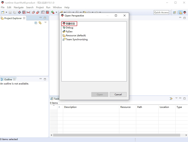
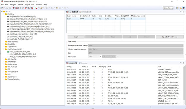
图5-1 测量标定界面 Measurement Calibration Interface
5.2 配置生成hex文件Configure the generation of hex files
点击生成hex文件按钮——>点击Insert按钮进行配置相关信息——>勾选Enable
勾选Enable是为了使能生成hex文件,如果不勾选则不会生成hex文件
Click the 'Generate hex file' button ->Click the 'Insert' button to configure relevant information ->Check 'Enable'
Checking Enable is to enable the generation of hex files. If not checked, hex files will not be generated

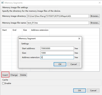
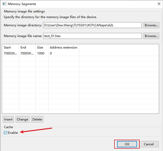
图5-2配置生成hex文件Configure the generation of hex files
5.3 连接并配置设备Connect and configure devices
连接设备,让设备通道处于开启且在线状态。
配置好之后左侧界面会显示A2L文件。
Connect the device and keep the device channel open and online.
After configuration, the left interface will display the A2L file

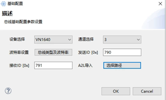
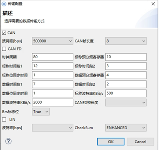
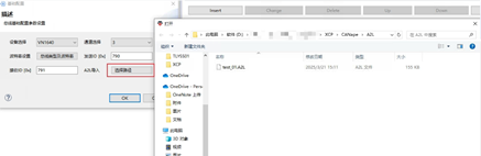
图5-3-1连接并配置Connect and configure
图5-3-2配置连接成功后的A2L文件界面显示
Display the A2L file interface after successful configuration connection
5.4 配置事件列表Configure event list
选择Event配置列表——>点击Update From Device按钮。
点击按钮之后会读取ECU中的事件信息并更新到界面上
Select the Event configuration list ->click the Update From Device button.
After clicking the button, the event information in the ECU will be read and updated on the interface
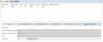
图5-4配置事件列表Configure event list
5.5 配置DAQ列表Configure DAQ List
选择DAQ配置列表——>点击Insert按钮进行配置
Select DAQ configuration list ->Click the Insert button to configure
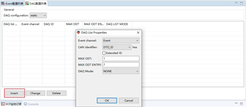
图5-5配置DAQ列表Configure DAQ List
5.6 测量measure
测量时可选择不同的测量方式(polling或者daq)
Different measurement methods (polling or daq) can be selected during measurement
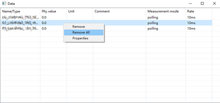
打开A2L文件——>选择所需测量的相关参数添加到测量窗口——>选择测量的方式(Polling/DAQ)——>点击开始测量按钮
Open A2L file ->Select the relevant parameters to be measured and add them to the measurement window ->Select the measurement method (Polling/DAQ) ->Click the start measurement button
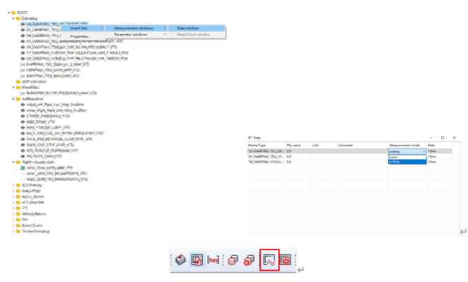
图5-6-1测量measure
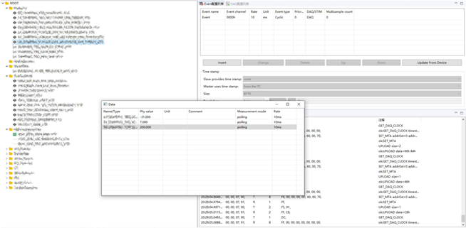
图5-6-2开始测量并成功发送接收数据界面
Start measuring and successfully sending and receiving data interface
如需停止测量可以点击停止测量按钮
To stop the measurement, click the stop measurement button

图5-6-3停止测量按钮Stop measurement button
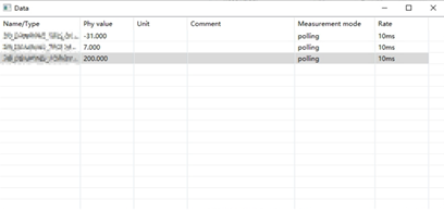
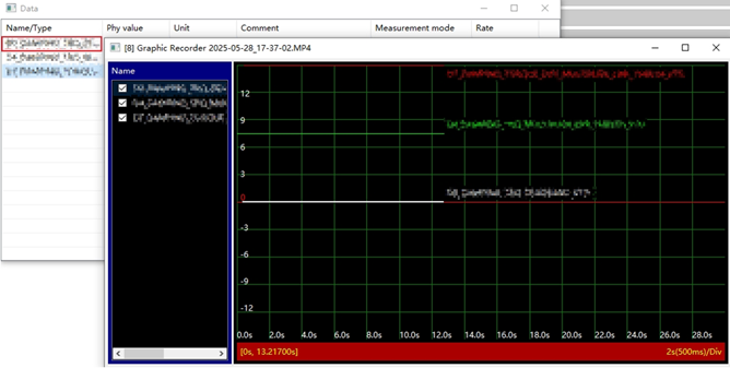
图5-6-4测量窗口measure window
单击变量名,可以加到曲线图显示:
Click the variable name to add it to the curve display:
5.7 标定calibration
打开A2L文件——>选择所需标定的相关参数添加到标定窗口——>双击进行修改值
Open A2L file ->Select the relevant parameters to be calibrated and add them to the calibration window ->Double click to modify the values
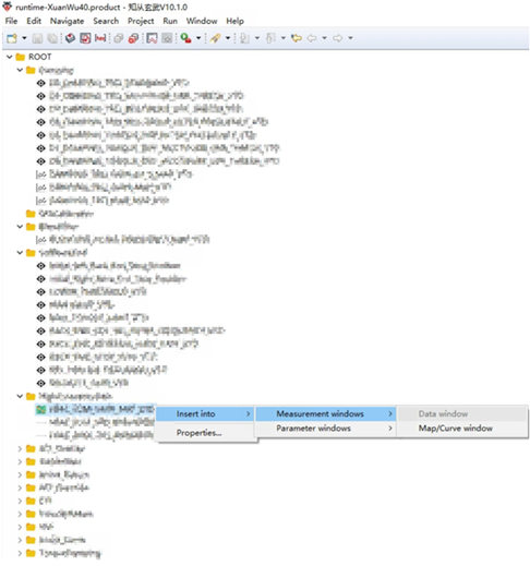
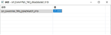
图5-7标定calibration
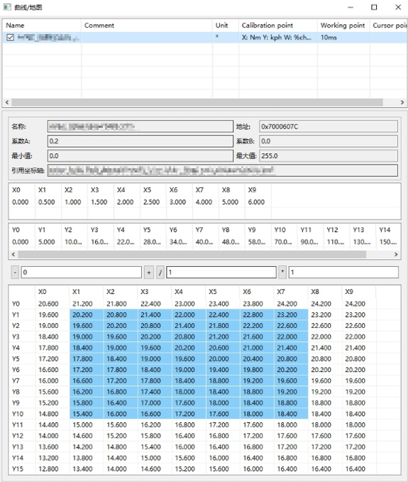
打开A2L文件——>选择所需标定的相关参数添加到标定窗口——>批量修改变量值
Open A2L file -> Select the relevant calibration parameters and add them to the calibration window -> Batch modify variable values
点击X0/Y0可以选中整列/整行:
Click X0/Y0 to select the entire column/row:
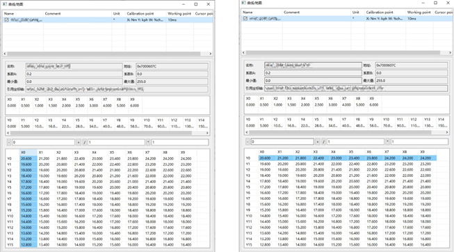
鼠标拖拽可以选中一片区域
Drag the mouse to select an area.
6 功能对比Feature comparison
支持的硬件 | ||
硬件名称 | 知从玄武 | Canape |
Vn1640/1630/5610 | √ | √ |
√ | ||
Peak PCANPT32 | √ | |
Kvaser | √ | |
ZLG USBCANFD | √ | |
TsMaster | √ | |
表6-1 硬件设备
支持的功能 | ||
功能描述 | 知从玄武 | Canape |
支持总线CAN (FD)、Ethernet、LIN, | √ | √ |
Trace窗口中的总线通信分析 | √ | √ |
记录总线数据 | √ | √ |
标定文件解析[A2L文件、ELF文件] | √ | √ |
显示DAQ列表情况 | √ | √ |
通过XCP进行在线标定 | √ | √ |
通过XCP进行在线测量 | √ | √ |
支持离线标定 | √ | √ |
标定变量曲线图展示 | √ | √ |
表6-2 支持功能
7 产品特点Product Feature
1、操作简易Easy to operate
图形化界面,方便配置
Graphical interface for convenient configuration
自动解析A2L文件
Automatically parse A2L Files
支持elf解析,和A2L文件同步地址段
Supports elf parsing and synchronizing address ranges with A2L files
2、使用灵活Flexible to Use
支持CAN、CAN FD、以太网标定
Supports CAN, CAN FD and Ethernet Calibration
支持XCP 1.1协议
Supports XCP 1.1 protocol
支持多种硬件接口
Supports various hardware interfaces
支持多种测量和标定方式
Supports a variety of measuring and Calibration specifications
 收起
收起


收起
收起


1 概述
玄武上位机软件用来将电子控制器中的应用程序和数据,从PC端下载到电子控制器上。支持UDSonCAN、UDSonEth、UDSonK-Line、UDSonLIN协议。提供客户协议定制集成,广泛应用在电子控制器产品开发阶段,测试阶段,售后服务阶段。
知从玄武程序刷新与诊断测试工具可应用于OEM和Tier1多种应用场景下。用户可以方便的在实验室,试验车辆以及实车上方便的进行程序刷写工作。
玄武上位机软件目前应用于各类电子控制器的程序刷写:
Ø 车身控制器 (BCM)
Ø 空调控制器
Ø DC/DC控制器
Ø 电子助力转向控制器
Ø 发动机控制器 (EMS)
Ø 变速箱控制器 (TCM)
Ø 电池管理系统 (BMS)
Ø 整车控制器 (VCU)
Ø 电机控制器 (MCU)
Ø 电动助力转向系统 (EPS)
Ø 防抱死制动系统 (ABS)
Ø 电子稳定性控制程序 (ESP)
Ø 主动防撞系统 (ACC)
Ø 牵引力控制系统 (TCS)
Ø ADAS控制器
2 以太网刷写介绍
在智能网联汽车发展的时代潮流中,随着处理器运算能力与硬件性能的快速提升,众多创新在汽车领域得以迅速落地。汽车电子控制器在整车中的占比持续攀升,与之相应的是,连接 ECU 的网络带宽需求也大幅增加,这一需求已远远超过 CAN 等传统车载网络的容量上限。此外,随着车辆网联化、智能化进程的推进,云计算与大数据技术的应用,以及高级驾驶辅助系统(ADAS)的广泛普及,构建全新的电子网络总线平台已成为新一代汽车发展的必然选择。
传统的车辆诊断通常依赖于专用的诊断工具和设备,限制了远程诊断和跨设备的兼容性。随着互联网协议(IP)的普及,DOIP作为一种基于IP的诊断技术应运而生,它支持通过以太网和Wi-Fi等标准网络进行通信,能够更快速、更灵活地进行远程诊断。
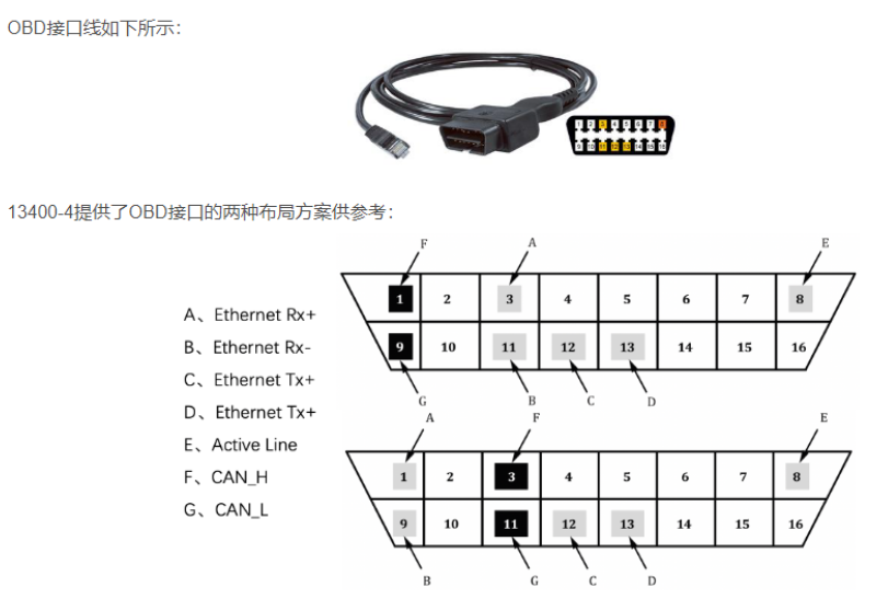
2.1 物理层 Physical Layer
100Base-Tx,OBD接口如下:
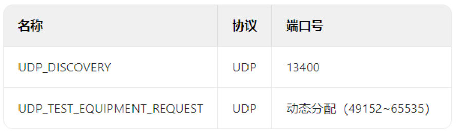
2.2 TCP/UDP层 TCP/UDP Layer
TCP 是一种可靠的传输层协议,它确保数据包正确无误地从源传输到目的地。在 DoIP 中,TCP 用于需要高可靠性的诊断通信,如 ECU 编程。TCP 通过三次握手过程建立连接,确保两端的通信是同步的,并且通过序列号和确认应答机制保证数据的顺序和完整性。
Ø 车内所有 DoIP 实体均应实现 TCP;
Ø TCP 使用一对端口号来标识连接,TCP 连接时目的端口应当是 TCP_DATA;
Ø DoIP 实体应在创建 socket 之后监听 TCP_DATA,用于与试图连接 DoIP 实体的外部测试设备建立通信;
Ø 外部测试设备应支持多个 TCP_DATA socket,本地端口将在创建 socket 时自动选择,远程端口应为 TCP_DATA。
UDP 是一种无连接的协议,它允许数据包在没有事先建立连接的情况下发送。这种方法减少了开销,使得通信更快,但也牺牲了可靠性。在 DoIP 中,UDP 用于那些不需要确认的服务,如车辆发现或基本诊断请求。
车内所有 DoIP 实体均应实现 UDP当需要外部设备对车辆 IP 节点进行广播或多播消息请求时,由于 TCP 的传输机制限制无法实现,因此须使用 UDP。
2.3 Doip 协议 Doip Protocol:
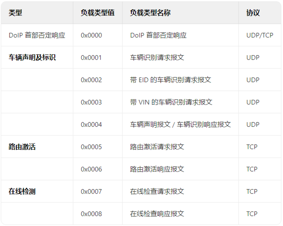
Doip总共有三类报文:节点管理类、诊断类和节点状态类。
负载类型 | 取值 |
节点管理类 | 0x0000 - 0x0008 |
诊断类 | 0x8001 - 0x8003 |
节点状态类 | 0x4001 - 0x4004 |
预留 | …… |
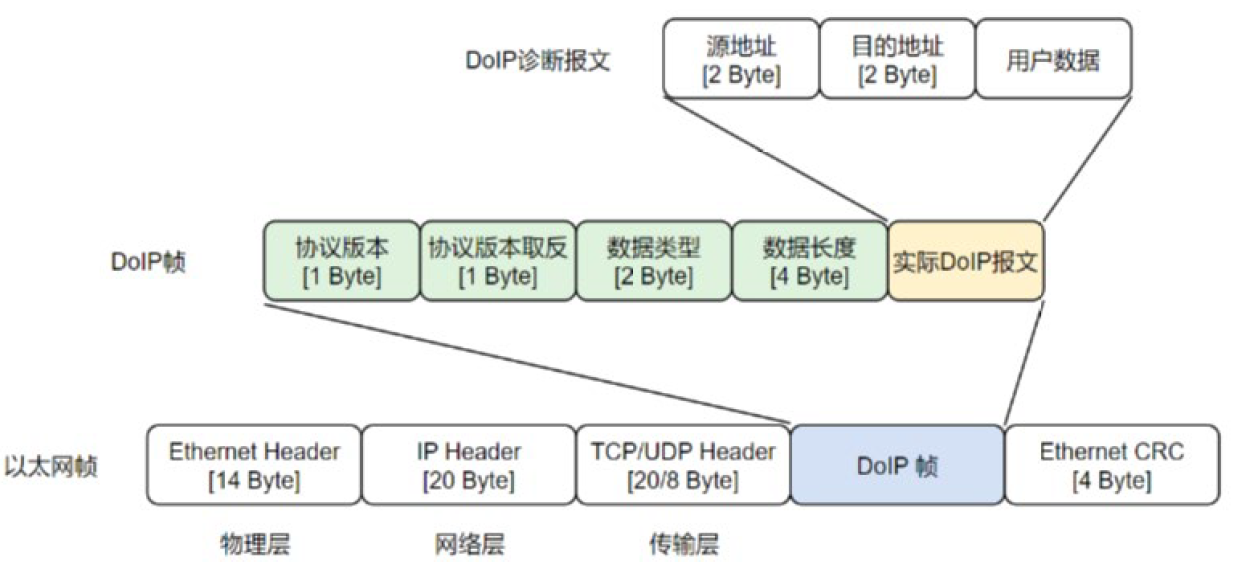
Doip在 OSI 模型中位于传输层,故 Doip报文发送前要封装 ETH 首部、IP 首部及 TCP/UDP 首部,Doip数据作为 SDU 层层向下传递,直至构成完整的以太网帧,通过物理层的介质发送出去。封装格式如下所示:
3 玄武Doip刷写介绍
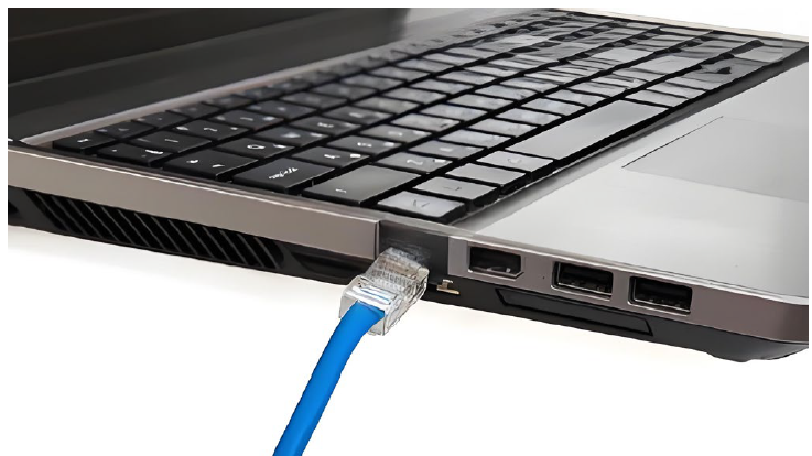
3.1 硬件连接 HardWare Connect
将RJ45端口连到电脑端,另一端与ECU相连,另一端需要根据ECU当前端口进行适配,常见端口有RJ45或者OBD。
3.2 刷写配置 Flash Config
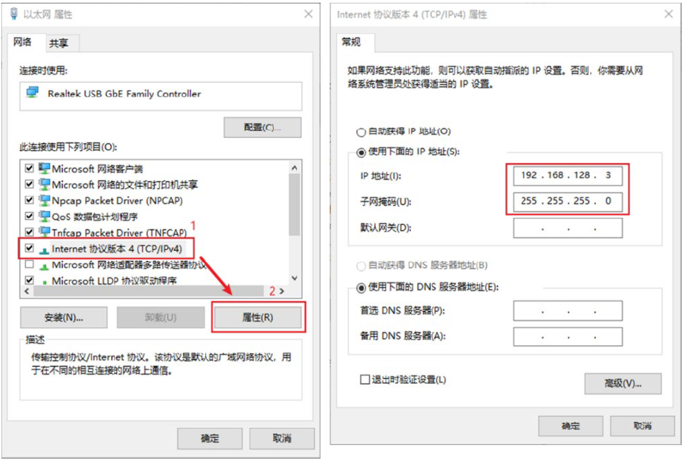
根据ECU当前的IP地址,在网络适配器中将电脑与ECU设置处于同一网段下。
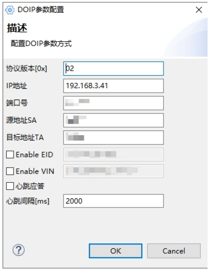
玄武打开以后,根据需要设置ECU的配置信息。
还可以对维持上位机和ECU之间的TCP连接进行心跳设置。
3.3 连接及刷写 Connect and Flash
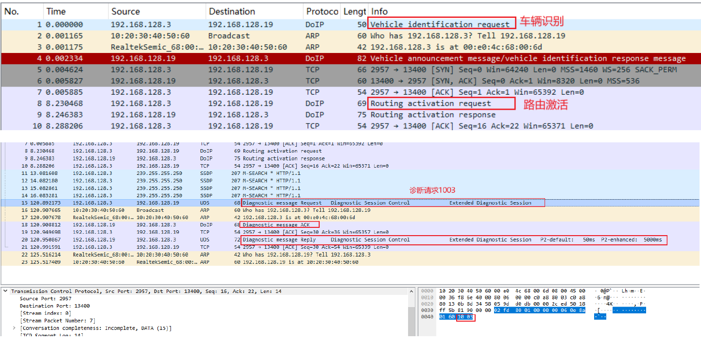
点击连接之后,玄武会自动发送车辆识别,路由激活等指令,成功和ECU建立连接之后,便可开始刷写。
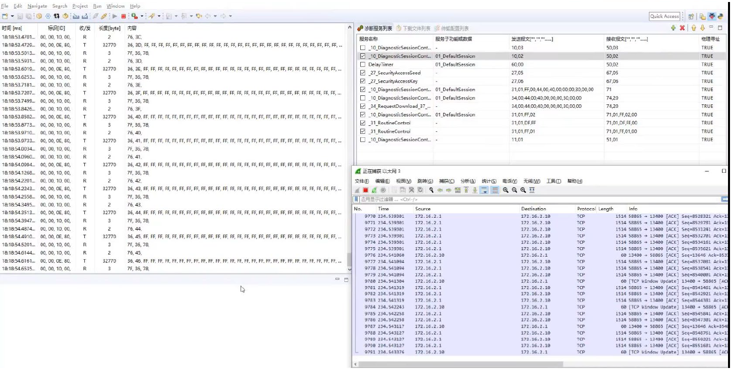
期间可通过WireShark工具进行抓包观察原始以太网报文。
4 证书
玄武软件著作权登记证书
收起
1 Overview
ZC.XuanWu upper computer software is used to download application programs and data from the PC to the electronic controller. It supports UDS on CAN, UDS on Eth, UDS on K-Line, and UDS on LIN protocols. It offers customized integration of customer-specific protocols and is widely used in the development, testing, and after-sales service stages of electronic controller products.
ZC.XuanWu program refresh and diagnostic testing tools can be applied in various application scenarios for OEMs and Tier 1 suppliers. Users can conveniently perform program flashing work in laboratories, test vehicles, and actual vehicles.
ZC.XuanWu upper computer software is currently used for program flashing of various electronic controllers:
Ø Body Control Module (BCM)
Ø Air Conditioning Controller
Ø DC/DC Converter
Ø Electric Power Steering Controller
Ø Engine Management System (EMS)
Ø Transmission Control Module (TCM)
Ø Battery Management System (BMS)
Ø Vehicle Control Unit (VCU)
Ø Motor Control Unit (MCU)
Ø Electric Power Steering System (EPS)
Ø Anti-lock Braking System (ABS)
Ø Electronic Stability Program (ESP)
Ø Active Collision Avoidance System (ACC)
Ø Traction Control System (TCS)
Ø Advanced Driver Assistance Systems Controller
2 Eth Flash Introduction
In the trend of the intelligent connected vehicle era, with the rapid development of processor computing power and hardware, many innovations have been rapidly promoted in the automotive environment. The proportion of automotive electronic products in the entire vehicle is also increasing day by day, and the network bandwidth demand for connecting ECUs has correspondingly increased significantly. This demand will far exceed the capacity limit of traditional in-vehicle networks such as CAN. In addition, with the advancement of vehicle networking and intelligence, the application of cloud and big data, and the popularization of advanced driver assistance systems (ADAS), building a new electronic network bus platform has become an inevitable task for the new generation of vehicles.
Traditional vehicle diagnostics typically rely on dedicated diagnostic tools and equipment, which limits remote diagnostics and cross-device compatibility.With the popularization of Internet Protocol (IP), DOIP (Diagnostic over IP), an IP-based diagnostic technology, has emerged. It supports communication through standard networks such as Ethernet and Wi-Fi, enabling faster and more flexible remote diagnostics.
2.1 Physical Layer
100Base-Tx,OBD接口如下:

2.2 TCP/UDP Layer
TCP is a reliable transport - layer protocol that ensures data packets are transmitted from the source to the destination accurately and error - free. In DoIP, TCP is used for diagnostic communications that require high reliability, such as ECU programming. TCP establishes a connection through a three - way handshake process to ensure that the communication at both ends is synchronized, and guarantees the order and integrity of data through sequence numbers and acknowledgment mechanisms.
Ø All DoIP entities in the vehicle shall implement TCP.
Ø TCP uses a pair of port numbers to identify connections. The destination port for a TCP connection shall be TCP_DATA.
Ø DoIP entity shall listen on TCP_DATA after creating a socket, which is used to establish communication with external test equipment attempting to connect to the DoIP entity.
Ø External test equipment shall support multiple TCP_DATA sockets. The local port will be automatically selected when creating a socket, and the remote port shall be TCP_DATA.
Unlike TCP, UDP is a connectionless protocol that allows data packets to be sent without establishing a prior connection. This approach reduces overhead, enabling faster communication, but sacrifices reliability. In DoIP, UDP is used for services that do not require acknowledgment, such as vehicle discovery or basic diagnostic requests.
All DoIP entities in the vehicle shall implement UDP.When external devices need to send broadcast or multicast message requests to vehicle IP nodes, since it cannot be achieved due to the limitations of TCP's transmission mechanism, UDP must be used.

2.3 Doip 协议 Doip Protocol:
There are three types of messages in Doip: node management, diagnostic, and node status.
负载类型 | 取值 |
节点管理类 | 0x0000 - 0x0008 |
诊断类 | 0x8001 - 0x8003 |
节点状态类 | 0x4001 - 0x4004 |
预留 | …… |

Doip is located at the transport layer in the OSI model, so before sending Doip packets, ETH headers, IP headers, and TCP/UDP headers need to be encapsulated. Doip data is passed down as SDUs layer by layer until a complete Ethernet frame is formed and sent out through the physical layer medium. The encapsulation format is as follows:

3 Xuanwu Doip flash introduction
3.1 HardWare Connect
Connect the RJ45 port to the computer end and the other end to the ECU. The other end needs to be adapted according to the current port of the ECU. Common ports include RJ45 or OBD.

3.2 Flash Config
Set the computer and ECU to be in the same network segment based on the current IP address of the ECU.

After opening ZC.XuanWu, set the ECU configuration information as needed.
It is also possible to set the heartbeat to maintain the TCP connection between the upper computer and ECU.

3.3 Connect and Flash
After clicking on the connection, Xuanwu will automatically send commands such as vehicle identification and route activation. Once a successful connection is established with the ECU, flashing can begin.

During this period, the WireShark tool can be used to capture and observe the original Ethernet packets.

4 CERTIFICATE

XUANWU SOFTWARE COPYRIGHT REGISTRATION CERTIFICATE
收起