- 知从青龙SecureBoot英飞凌TC2XX
- 知从青龙SPI OTA英飞凌TC397
- 知从青龙SecureBoot恩智浦S32K3 CHERY QSQR
- 知从青龙SecureBoot恩智浦S32K3
- 知从青龙FOTA方案
- 知从青龙BootLoader
- 知从青龙BootLoader恩智浦KW45
- 知从青龙SECUREBOOT英飞凌TC377
- 知从青龙FOTA英飞凌TC387
- 知从青龙瑞萨 RH850U2A 以太网刷写介绍
- 知从青龙Ethernet BootLoader RENESAS RH850U2A
- 知从青龙SecureBoot恩智浦S32K344产品
- 知从青龙FOTA英飞凌TLE9893
- 知从青龙Bootloader 英飞凌 TC213 SMTC
- 知从青龙Bootloader ST SPC58NN GEELY GEEA2.0
- 知从青龙Bootloader恩智浦NCJ29D5
- 知从青龙FOTA英飞凌TC3XX
- 知从青龙FOTA
- 知从青龙SecureBoot恩智浦S32K1XX
瑞萨RH850U2A MCU是瑞萨电子跨域 MCU 产品系列的首款产品,其架构设计支持EVITA Full 级别的信息安全功能,满足安全、快速的完全无等待 OTA软件更新的安全需求。该汽车控制微控制器采用双核锁步架构,最高可配置四组主频达400MHz的CPU核心。每个核心均集成硬件虚拟化辅助功能,支持多个不同ISO 26262功能安全等级的软件系统在高性能运行状态下实现互不干扰的独立运作,同时有效降低虚拟化带来的性能损耗,确保实时计算效能。RH850/U2A MCU集成多制式网络接口阵列,可高效处理ADAS及自动驾驶系统中多类型传感器生成的海量异构数据流。该设计为系统架构提供前瞻性支持,满足新一代高速率网络传输标准及严苛的通信带宽需求。
Ethernet OTA概述
Ethernet OTA的演进直接响应了汽车产业向"软件定义汽车"的转型需求。采用以太网的OTA方案,可将整车级软件刷新时间从CAN时代的7.2小时压缩至18分钟,同时支持A/B分区验证、数字签名校验等安全机制,符合UNECE R156法规对软件更新管理系统的强制认证要求。
Ethernet OTA技术作为智能汽车电子架构演进的核心支撑,其必要性主要体现在三个方面:首先,面对车载软件复杂度指数级增长,传统线下刷写方式已无法满足高频次的ECU固件更新需求;其次,ISO 21434网络安全标准强制要求车辆具备安全漏洞的72小时热修复能力;再者,自动驾驶算法迭代需50-100GB级数据包的可靠传输,这远超传统CAN/LIN总线的承载极限。
OTA架构概述
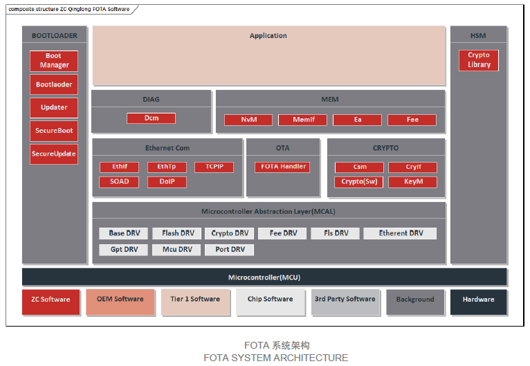
知从青龙Ethernet FOTA系统架构支持以太网通信场景下的FOTA功能,通过 TCP/IP、DoIP、SoAd、Dcm模块实现Ethernet通信UDS诊断刷写,并通过适配Crypto Library实现各OEM规范的信息安全需求。以下为各模块的功能描述:
Ø Bootloader
BootManager模块提供FOTA启动管理功能,支持适配软硬件SecureBoot功能,通过烧录和刷写存储Bootloader和Application的期望MAC值,启动阶段SecureBoot通过计算比较Bootloader和Application的MAC执行软件完整性校验,保证软件安全需求。
Ø Ethernet Com
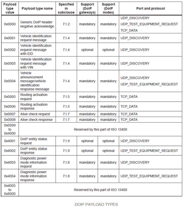
DoIP模块基于TCP/IP协议实现Ethernet通信收发功能,满足ISO 13400标准定义。通过车辆识别、路由激活、诊断消息功能实现UDS刷写流程,实现Ethernet OTA功能。
Ø Crypto、HSM
Ethernet OTA支持适配木牛加密库功能,支持非对称加密算法和加密算法结合实现安全刷写功能,适配证书认证功能满足安全诊断功能,适配HSM提高信息安全功能的稳定性和校验速度。
Ethernet刷写流程介绍
外部诊断设备与车内DoIP实体通过车辆识别、建立连接、路由激活完成通信连接,并通过发送诊断服务执行Ethernet OTA的诊断刷写功能。外部诊断设备与车内DoIP实体建立通信的流程如下图所示。
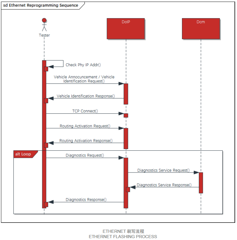
车辆发现流程的目的是将节点的DoIP属性告诉给当前局域网内其它DoIP节点。其它DoIP节点可根据当前节点的通信需求,决定是否与其建立通信连接:
a) 上电后,Client以广播方式主动发送 Vehicle Announcement Message / Vehicle Identification Request,在消息中携带逻辑地址、VIN、EID 等信息;
b) 收到该消息的 Server以单播的形式回复 Vehicle Identification Response 消息,其中携带逻辑地址、VIN、EID 等信息。
Client 与 Server在完成车辆识别后,通过建立TCP连接进行 UDS 通信:
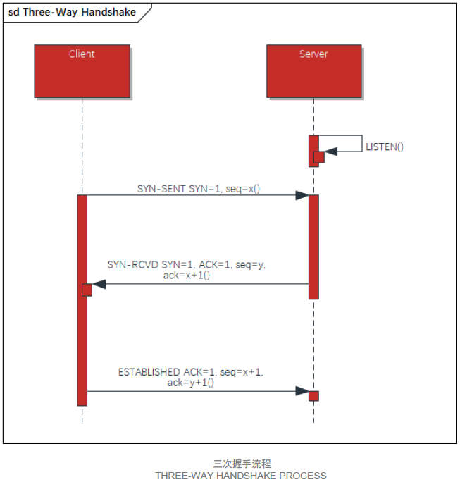
a) Client 通过三次握手主动与 Server 建立 TCP 连接:
l 第一次握手:客户端向服务器发送一个带有 SYN(同步)标志的数据包,该数据包中包含客户端选择的初始序列号(Sequence Number),表示客户端希望与服务器建立连接。
l 第二次握手:服务器接收到客户端的 SYN 数据包后,会向客户端发送一个带有 SYN 和 ACK(确认)标志的数据包。这个数据包中的序列号是服务器自己选择的初始序列号,而确认号则是客户端的序列号加 1,表示服务器已经收到了客户端的连接请求,并准备好与客户端建立连接。
l 第三次握手:客户端接收到服务器的 SYN+ACK 数据包后,会向服务器发送一个带有 ACK 标志的数据包,确认号为服务器的序列号加 1,表示客户端已经收到了服务器的响应,并且连接建立成功。此时,TCP 连接正式建立,客户端和服务器可以开始进行数据传输。
b) Client 发送 Routing Activation Request 消息请求激活路由,Server 根据实际情况同意或者拒绝激活请求,激活结果通过发送 Routing Activation Response 消息告知 Client。
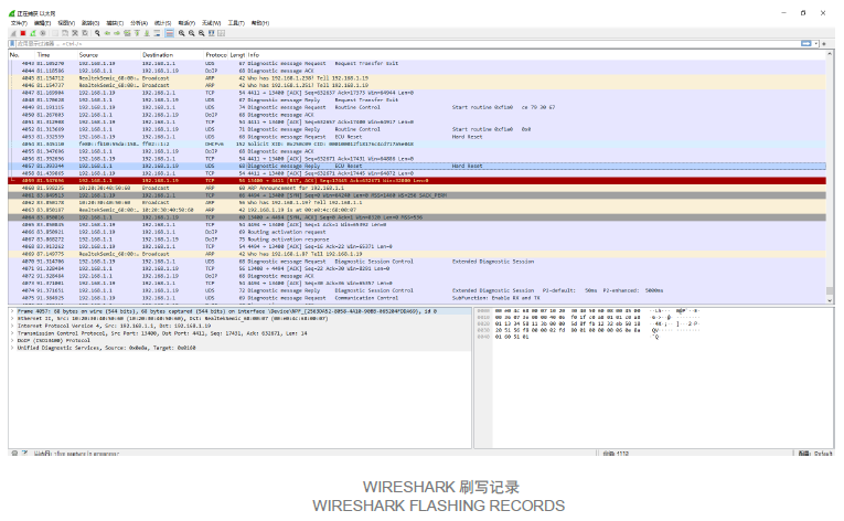
完成路由激活后,上位机通过DoIP协议发送诊断刷写请求,使用诊断消息(0x8001)、诊断确认消息(0x8002)、诊断否定确认消息(0x8003)等载荷类型进行交互,并按照刷写流程发送指定的诊断报文数据,诊断刷写流程与CAN刷写无较大差异。
Ethernet刷写相比较于CAN刷写,主要在于以太网的通信速率则高很多,常见的有 100Mbps、1000Mbps 甚至更高,能够以更快的速度传输数据,大大缩短了刷写时间。同时由于Ethernet通信采用星型拓扑结构,通过交换机等设备将各个节点连接起来。诊断设备与目标 ECU 通过以太网接口和网线进行连接,利用以太网交换机实现数据的交换和转发,可支持更多设备连接,网络扩展性更好,能更好地支持多节点并发刷写。
以太网的网络管理功能较为强大,可通过交换机实现 VLAN 划分、流量控制、端口绑定等功能。安全性方面,可采用 IP 地址过滤、MAC 地址绑定、SSL/TLS 加密等多种安全机制,能更好地保护刷写过程中的数据安全和网络安全。
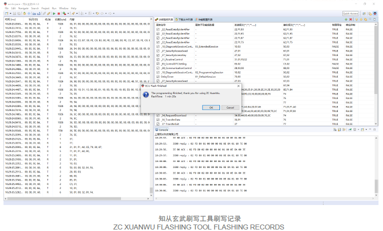
知从玄武上位机刷写工具支持Boot自动化测试:诊断服务测试、DID测试、鲁棒性测试、压力测试,能够针对刷写场景自由配置逻辑地址、VIN、EID等DoIP通信配置和诊断刷写流程,以下为知从玄武上位机刷写工具配置界面和刷写测试记录: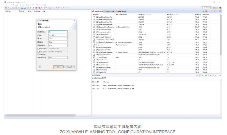
点击下载产品手册