- 知从木牛SafetyLibrary旗芯微FC7300
- 知从木牛SafetyLibrary旗芯微FC7240
- 知从木牛SafetyFrame赛普拉斯CYT2B7
- 知从木牛SafetyFrame瑞萨RH850/U2AX
- 知从木牛SafetyFrame瑞萨RH850F1KM
- 知从木牛BCC恩智浦MC33771
- 知从木牛SafetyLibrary恩智浦MPC5744P
- 知从木牛SafetyLibrary英飞凌TC377
- 知从木牛Safetylibrary意法半导体SPC58NH
- 英飞凌TC3XX_MTU模块介绍以及使用方法
- 知从木牛SafetyFrame瑞萨RH850/P1M-C
- 知从木牛SAFETYFRAME瑞萨RH850/U2CX
- 知从木牛SAFETYLIBRARY旗芯微FC7300F8MDQ
- 知从-云途YTM32B1H/M功能安全库SAFLIB产品
- 知从木牛-恩智浦FS26功能安全
- 知从木牛SafetyLibrary意法半导体SPC58NN
- 知从木牛复杂驱动CDD恩智浦MC33774
- 知从木牛SafetyFrame
- 知从木牛SafetyLibrary恩智浦MPC5746C
- 知从木牛SafetyLibrary恩智浦MPC5748G
- 知从木牛SafetyLibrary软件平台恩智浦S32K14X
- 知从木牛SafetyLibrary英飞凌TC2XX
- 知从木牛SafetyLibrary英飞凌TC275
- 知从木牛SafetyLibrary英飞凌TC397
- 知从木牛SBC恩智浦FS6500-FS4500
- 知从木牛SBC英飞凌TLF35584
MTU (Memory Test Unit)控制和监控设备内各种存储器的测试、初始化和数据完整性检查功能。该平台中的每个SRAM周围都有一些数字逻辑,称为SRAM支持硬件(SSH)。SSH是一个硬件块,它控制内部存储器的错误检测和纠正,内存内置自检(MBIST)。每个SSH块提供一个统一的接口来控制其各种功能。有多个这样的SSH实例,每个实例控制一个或多个不同的内部内存。AurixPlus平台中的内存测试单元(Memory Test Unit, MTU)提供了寄存器接口来配置和控制这些不同的内存控制器。
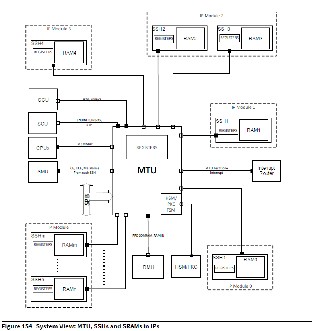
MTU系统视图
系统中不同的IP模块(如CPU、LMU、CAN等)内部可能有一个或多个SRAM。每个SRAM周围都有自己的SSH模块,有自己的寄存器(SRAM支持硬件(SSH)寄存器)和MBIST逻辑。每个SSH通过内部接口分别连接到MTU。MTU本身连接到SPB总线,并且每个SSH的寄存器可以通过这个SPB接口访问。每个SPB访问都由MTU在内部转发(和返回)到(或从)相应的SSH。
MTU 功能特性
1.提供到内部SSH实例的统一接口。
– MTU提供一个统一的寄存器接口用于控制每个内部SSH实例的操作和功能。
– 系统中每个SRAM的各种可配置的测试类型可以通过MTU控制。
2.数据初始化
– 系统中每个SRAM块都能通过MTU进行硬件初始化。
– Security-Sensitive存储器可以自动初始化,防止通过MTU将数据读出。
3.内存错误纠正和检测
– 系统中每个SRAM的内存错误纠正和检测都能通过MTU配置。
– 可纠正的和不可纠正的错误检测。
– 地址错误检测。
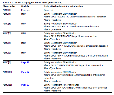
4.SMU警告通知
– 来自SRAM/SSH的3个警告(CE alarm, UCE alarm and ME alarm)被发送到MTU,然后被MTU转发到SMU。
SSH使能
AurixPlus平台中的每个SSH在MTU_MEMTESTx (x=0-2)寄存器中都有一个与之相关的启用位。在AurixPlus平台中实现的SSH启用位的MEMTESTi (i=0-2)寄存器。只有当SSH启用时,每个SSH的控制寄存器才可访问(MTU_MEMTEST.MEMx_EN = 1)。唯一的例外是寄存器MCi_ECCS (i=0-95), MCi_ECCD (i=0-95)和MCi_ETRRx (i=0-95;x=0-4), MCi_ERRINFOx (i=0-95;x=0-4), MCi_ALMSRCS (i=0-95)和MCi_FAULTSTS (i=0-95)(在每个SSH实例中),它们在任何时候都可以允许容易的运行时访问ECC特性,即这些特定的寄存器(即。ECCS、ECCD、ETRRx、ERRINFOx、ALMSRCS和FAULTSTS)可以读写,唯一的前提条件是MTU时钟通过MTU_CLC寄存器使能。只有通过MEMTEST寄存器使能SSH时,才能访问SSH的所有其他寄存器,否则MTU将返回SPB错误。对于某些SSH,通过MEMTEST寄存器启用或禁用SSH可能会根据配置导致整个或部分内存被自动初始化。这个自动初始化可能需要数百个时钟周期来完成。在此期间,不能访问SSH寄存器(甚至不能访问通常不需要启用SSH的寄存器),并且任何对运行自动初始化的SSH的寄存器访问都将导致SPB总线错误。注意,在通过MTU访问任何SSH寄存器之前,必须通过CCU寄存器启用包含SRAM的模块的时钟输入。除了这个CCU时钟配置之外,不需要启用模块时钟(例如,使用CLC寄存器)来访问SSH寄存器。
Note:
1. 当启用SSH时,对内存的功能访问暂时不可用。当一个内存正在被测试时,软件应该阻止对该内存的功能性访问(例如,在测试CPU的本地内存时,CPU应该处于空闲状态,或从其他内存执行)。
2. 正确执行SSH操作(例如MBIST测试)要求MTU和包含待测内存的模块在SSH操作期间都是可操作的(例如:测试)。当启用SSH时,包含待测内存的模块的重置可能会导致意外行为。软件必须注意,当启用SSH时,诸如应用程序重置、模块重置、备用条目、时钟频率改变等事件不会被触发。例如,模块复位可能会导致模块在复位后尝试正常访问SRAM,而SSH仍然是启用的(因此功能访问是禁用的),这样的场景必须通过软件来避免。
3. 当模块复位时,如果MTU和SSH之间的通信正在进行(例如SSH寄存器读或写),通信将被中止,并在几个周期内立即在SPB上触发总线错误,没有任何超时。只有正在进行的读写可能被破坏,未来的通信不会受到影响。
4. 如果访问了无效的SSH寄存器(例如,在一个SSH实例中不存在的寄存器,或一个不存在的SSH实例),这将导致SPB上的总线错误。
Security-Sensitive存储器和自动初始化
对于TC3XX平台,以下内存属于Security-Sensitive内存。
1. CPUx_DMEM(x = 0 - 5) – 仅内存的缓存部分属于Security-Sensitive内存
CPUx_DMEM(x = 0 - 5) - Only the cache part of the memory is considered security sensitive.
2. CPUx_DTAG(x = 0 - 5)
3. CPUx_PMEM(x = 0 - 5) – 仅内存的缓存部分属于Security-Sensitive内存
CPUx_PMEM(x = 0 - 5) - Only the cache part of the memory is considered security sensitive.
4. CPUx_PTAG(x = 0 - 5)
对于以上Security-Sensitive内存,MTU必须阻止通过SSH去读写这些内存。对于安全应用程序,Security-Sensitive内存可以通过自动初始化以擦除现有内容。这是由DMU中的PROCONRAM寄存器控制的。
如果PROCONRAM.RAMIN = 00、01或10,则启用自动内存内容初始化。PROCONRAM配置初始化是由冷复位触发,还是由热复位触发,或者两者都触发。在这些模式中,只要对应的MTU_MEMTEST,也会触发Security-Sensitive内存的自动初始化。MEMx_EN或MTU_MEMMAP被更改(即,如果内存映射模式被更改,则相应的SSH被启用或禁用)。MEMSTATi (i=0-2)寄存器位表示MEMTEST状态的改变是否触发了内存x的自动数据初始化。MEMx_EN或MTU_MEMMAP和初始化序列尚未完成。如果MEMSTAT寄存器中的MEMx_AIU位被设置,这意味着该内存的自动初始化仍在进行中。在启动Auto-initialization后,SSH才会启用,在启动Auto-initialization前,SSH才会禁用。软件可以通过轮询这个位来等待自动初始化完成。
如果PROCONRAM.RAMIN=11,则复位时不自动初始化RAM内容,当SSH模块启用或禁用MTU_MEMTEST时,不自动初始化RAM内容。MEMx_EN或MTU_MEMMAP寄存器位。这允许应用程序使用SSH(例如,用于错误注入,数据修改或运行时内存测试),而不会损坏内存内容。
SSH操作
内存测试启动
每个内存测试的启动是通过写入对应SSH寄存器MCONTROL.START位来启动。在启用MCONTROL.START位之前,需要正确配置配置寄存器MCi_CONFIG0 (i=0-95), MCi_CONFIG1 (i=0-95)。
1. CONFIG0.ACCSTYPE指定将在当前内容的每个单一地址上执行的访问类型(read/write)。
2. CONFIG0.NUMACCS指定当前内容中单个地址的访问总数。
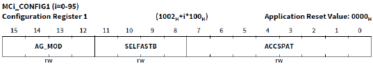
3. CONFIG1.ACCSPAT指定访问模式。
4. CONFIG1.AG_MOD指定SSH使用复杂的寻址方案。
5. CONFIG1.AG_MOD指定配置测试为无创测试。当使用无创测试时,MSTATUS.FAIL是不固定的,此时软件必须检测 ECCD, ETRR , ERRINFO寄存器是否在测试过程中检测到任何错误。
内存测试完成由MSTATUS.DONE=1标识。如果测试失败,则MSTATUS.FAIL位会被置起。Note:如果测试序列由于中间故障而停止测试,那么MSTATUS.DONE不会置1。
内存测试完成中断
MTU为中断路由器(IR)提供一个中断。中断表示所有正在运行的测试已经完成。该信号复位值高。当对任何SRAM的测试开始时,该信号变为低电平。在所有正在进行的测试完成后,这个信号再次变高,并且这个上升沿触发中断。
获取详细的内存测试结果
MSTATUS.FAIL 和 MSTATUS.DONE (可以通过 MEMDONEi (i=0-2) 寄存器从MTU本身轮询)位提供了测试通过/测试失败的信息和测试完成状态。
如果MCONTROL.FAILDMP = ‘1’,测试在失败后停止,故障信息立即用于转存。 MSTATUS.FDA用于失败转存。任何转存信息只能在RDBFL 和 ETRR(0)查询。RDBFL 包含失败位映射,ETRR包含失败地址。
读取MSTATUS和RDBFL(n-1)寄存器,当 MSTATUS.FDA = ‘1’时,将会复位MSTATUS.FDA 成0。MCONTROL.RESUME后续设置将会恢复中断测试序列。
范围寄存器可用于对不断移动的内存范围运行连续测试,以便最终分析完整的内存。
内存测试期间的故障注入。
l 非破坏性测试:通过ECCMAP编程一个带有错误ECC的Word来产生数据错误。
l 破坏性测试:通过RANGE.INJERR位来注入故障,RANGE.INJERR=1 和 RANGE.RAEN=1时,将RANGE.ADDR字段作为一个指向SRAM位置的指针,在测试期间不会对该地址进行写访问。在测试之前,用软件写一个特定的值(使用RDBFL寄存器使用单个SRAM写访问),然后使用RANGE.INJERR&&RANGE.RAEN=1进行测试。
l 数据错误:
1. 测试在全地址运行,RANGE.ADDR指定的地址不执行写访问,导致测试过程中与其数据不匹配导致测试失败。
2. 注入错误后,所有正常的诊断和通知都能被测试,Alarm能够被触发,在非破坏性测试期间,能够在 ETRR/ERRINFO中跟中错误。
3. 在测试中,FAIL位能够被置位,当FAILDUMP = 1时,能够获得 fail bitmap同时FDA会被置位。
4. fail bitmap是简单的(预期数据模式)XOR(实际数据模式)。
l 地址错误:通过简单地将SFLE位设置为1,在测试期间触发地址错误。注意,这将触发来自每个地址的地址错误,并且在非破坏性测试期间,导致ETRR/ERRINFO被地址错误填充。
用定义的内容填充内存
SSH可以用定义的模式快速的对部分内存或者整个内存进行填充。例如使用MCONTROL.DINIT位,每个周期有一次写访问,具有完整的内存数据宽度。因此,必须确保MCONTROL.SRAM_CLR=0。
首先,在设置MCONTROL.DINIT之前,软件需要用所需的位模式填充 RDBFL寄存器(具体参考 MCi_RDBFLy (i=0-95;y=0-66))。在此模式下,不强制要求具有有效的ECC码。
其次,设置RANGE寄存器,设置为需要填充模式的内存范围。
接下来,将 MCONTROL.DINIT 和 MCONTROL.START设置为开始初始化RAM。然后软件需要清除 MCONTROL.START位。当 MSTATUS.DONE被硬件设置为1时,表示内存填充操作完成。
注意:对某些SRAM,不支持这种使用DINIT位的SRAM初始化的方法。
初始化RAM
使用MCONTROL.SRAM_CLR位可以初始化整个SRAM,所有的SSH和SRAMS都支持初始化。
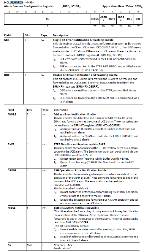
l 使能SSH,MEMTESTx.MEMxEN = 1。注意:使能动作会触发UCE告警,需要在使能前通过设置ALMSRCS.OPENE来关闭告警。
l 设置MCONTROL.SRAM_CLR位。
l 使用MCONTROL.START来开启初始化。
l 等待MSTATUS.DONE 复位和清除MCONTROL.START位。
l 通过轮询MSTATUS.DONE位来等待初始化结束。
l 清除MCONTROL.SRAM_CLR,并离开测试模式。
通过初始化,整个SRAM被ECC正确的零值填充。清除初始化引起的UCEE和OPERR故障标志,重新启用ALMSRCS.OPENE。
读取单个内存位置
SSH还可以用于读取单个单词的内容。RDBFL寄存器保存完整内存字的内容,因此可以读取所有内存位,包括ECC或奇偶校验位。
必要的步骤是:
1. 进入内存测试模式。
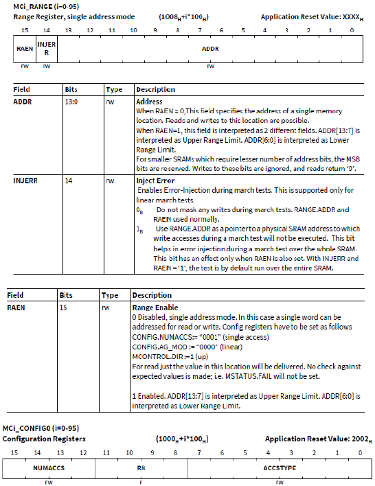
2. 初始化寄存器RANGE.RAEN=0,RAEN指定地址访问模式,0表示单地址访问模式且单个内存地址可读可写;CONFIG0.NUMACCS = 1,NUMACCS = 1表示每个地址的访问次数;CONFIG0.ACCSTYPE =1,ACCSTYPE表示访问类型,1表示读访问;CONFIG1 = 0, AG_MOD表示地址生成器模式,0代表使用线性地址生成运行测试,SELFASTB指定选择快速位,0表示正常寻址序列位0在正常位置,ACCSPAT=0指定访问模式。
3. MCONTROL = 0x4009 (FAILDMP = 0, direction up, start):开始读操作。MSTATUS.DONE将被清除。
4. MCONTROL = 0x4008,清除启动位。
5. 等待MSTATUS.DONE再次置位(也可以轮询MEMDONEi (i=0-2)寄存器状态)
6. 读取RDBFL寄存器数据
7. 脱离内存测试模式
8. 清除UCERR和OPERR故障标志(开启测试前需要关闭故障告警)
写入单个内存位置
SSH还可以用于写入单个单词的内容。RDBFL寄存器保存完整内存字的内容,因此可以读取所有内存位,包括ECC或奇偶校验位。
必要的步骤是:
1. 进入内存测试模式。
2. 初始化寄存器RANGE.RAEN=0,RAEN指定地址访问模式,0表示单地址访问模式且单个内存地址可读可写;CONFIG0.NUMACCS = 1,NUMACCS = 1表示每个地址的访问次数;CONFIG0.ACCSTYPE =0,ACCSTYPE表示访问类型,0表示写访问;CONFIG1 = 0, AG_MOD表示地址生成器模式,0代表使用线性地址生成运行测试,SELFASTB指定选择快速位,0表示正常寻址序列位0在正常位置,ACCSPAT=0指定访问模式。
3. MCONTROL = 0x4009 (FAILDMP = 0, direction up, start):开始读操作 MSTATUS.DONE将被清除。
4. MCONTROL = 0x4008,清除启动位。
5. 等待MSTATUS.DONE再次置位(也可以轮询MEMDONEi (i=0-2)寄存器状态)
6. 脱离内存测试模式
7. 清除UCERR和OPERR故障标志(开启测试前需要关闭故障告警)
复位后的告警处理
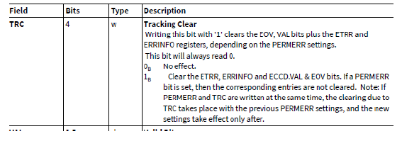
当一个告警产生时,系统可能会进行复位。ECCD寄存器中的告警状态位(ECCD.CERR,UCERR和MERR)在复位后被清除,但错误状态位(ETRR,ERRINFO和FAULTSTST寄存器)仍然有用,错误状态位只能通过软件清除,并只能通过热PORST复位。
通过应用程序复位,告警本身也会被清除。这可以防止单个警报复位循环。
安全特性
SRAM、SSH和MTU实现的安全特性:
1. 错误检测和纠正码/逻辑。
2. 地址错误监控。
3. SRAM多路复用因子。
4. 错误跟踪寄存器。
5. 临界寄存器位的安全触发器。
MBIST检测应用示例
编程步骤:
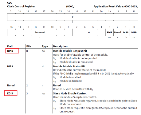
1. 使能MTU接口:CLC. DISR = 0,CLC.EDIS = 1。
2. 清除SSH故障信息:MCi_ECCD.TRC = 1(i:0-95)。
3. 清除SMU故障信息:Smu_ClearAlarmStatus。
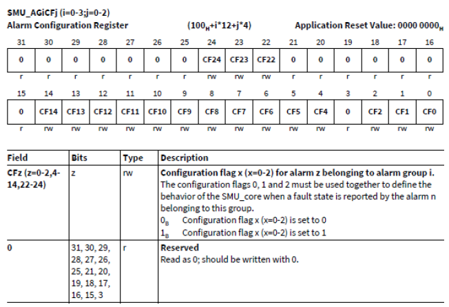
4. 关闭SMU告警动作:SMU_AGiCFj = 0。
5. 初始化SSH(Initializing SSH):
1. 关闭ALMSRCS. MISCE和OPENE故障检测。
2. 配置MEMTESTi(i:0-2),使能对应SSH。
3. 轮询MEMSTAT0寄存器,等待SSH的SRAM自动初始化完成。
4. 设置CONFIG0 = 0x4005(NUMACCS = 4,ACCSTYPE = 5), CONFIG1 = 0x5008(ACCSPAT = 8, AG_MOD = 5)。
5. 开启SRAM测试,MCONTROL. START = 1。
6. 清除开启标志位,MCONTROL. START = 0。
7. 轮询MSTATUS.DONE,等待SRAM测试完成。
8. 查看ECCD寄存器的SERR,CERR,MERR,EOV故障。
9. 查看ERRINFO和ETRR寄存器获取故障信息。
10. 清除故障信息,ECCD.TRC = 1。
ZC TC3XX SafetyFrame产品介绍
汽车电控系统的电气化、智能化发展日趋复杂,对于电子电气架构的安全性要求也越来越高。通过对道路车辆应用场景的HARA分析,为了使安全目标被降级分解、保持危害发生可能性低于风险的受限值,汽车功能安全越来越受到重视。近年来,在功能安全标准上参考ISO 26262;在软件架安全架构上参考E-GAS分层。在电子电气系统中,对于通用的Element通常采用SEooC(safety element out of context)方法进行设计开发。
知从科技推出SAFETY FRAME为各车载控制器客户提供ASIL等级分解咨询、FMEDA分析过程支持、芯片级自检安全机制开发、SafetyFrame配置与软件集成等全流程功能安全服务。
SAFETY FRAME 包括 3个组件:MCU 内部模块自检测试组件(即 SF.MCU)、 SBC 硬件安全机制的驱动组件(即 SF.SBC)、安全架构组件(即SF.Architecture)。SF.Architecture 的核心模块为 Test Manager,用于 MCU&SBC 的 Safety Library 调度管理,包括 Safety Wdgm、Safety SBC/ASIC 驱动模块调度、与应用层 PFC(Program Flow Check)接口等,SF.MCU包含 3 大模块:
l TestLib--实现 MCU 芯片模块的检测。
l DriverLib--实现 MCU 芯片模块的驱动。
l SwLib--用户常用的数字签名库、端到端保护库等接口。
SAFETY FRAME 在软件模块化分层原则上,将 Function Controller 和 Monitoring Controller 分别由 SF.MCU 和 SF.SBC 实现,并部署在 EGAS Level2 和 Level3 层级,充分考虑了程序流监控和关断路径设计的应用需求。
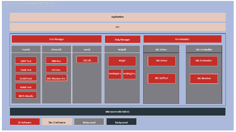
软件架构
知从SafetyFrame产品实现的功能安全模块包括:Test Manager模块、LBIST Test模块、MBIST Test模块、PFlash Test模块、MCU Firmware Test模块、Register Test模块、DMA Test模块、SRI Error Handling模块、MONBIST Test模块、Mcu Register Monitor模块、Register Monitor Test模块、Evadc Test模块、Interrupt monitor Test模块、Clock Plausibility Test模块、DAM Test模块、Convctrl Test模块、CPU Internal BUS Test模块、STM Test模块、GTM TIM Clock Test模块、Gtm IOM Alarm Test模块、Gtm Tom Tim Test模块、Port Test模块、GptTst模块、PMS configuration模块、DTS Configuration模块、OSC Clock Monitor模块、SMU Error Handler模块、SMU Software Alarm Drv模块、IR FFI Control模块、GTM IOM Configuration模块、ERU Configuration模块、TLF35584 Driver模块、TLF35584 Error Handler模块、E2E保护模块、Safe Watchdog Manager模块、Safe Watchdog Interface模块、Safe Internal Watchdog模块、Safe SBC Watchdog模块。
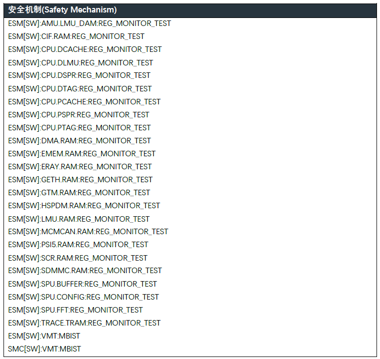
知从SafetyFrame产品针对本文中提及的TC3XX MTU模块实现了内存自检MBIST模块,以及寄存器自检RegMonTst模块,模块实现了以下安全机制。
点击下载产品手册