1 OVERVIEW OF SAF
The S32K3 safety software is an official software package provided by NXP, designed to help customers meet functional safety requirements for automotive electronic control unit products based on the S32K3 microcontroller. The S32K3 safety software fulfills most chip-level functional safety requirements specified in the S32K3xx Safety Manual, which includes SAF (Safety Application Framework), SPD (Safety Peripheral Driver), SCST (Core Self-Test Code), and RTD (Real-Time Drivers).
The S32 Safety Software Framework provides multiple software modules at both hardware safety layer and service safety layer, as follows:
l BIST: Power-on self-test management module, including Logic Built-In Self-Test (LBIST) and Memory Built-In Self-Test (MBIST).
l eMCEM: Extensible Microcontroller Error Management module, which integrates the FCCU (Fault Collection and Control Unit) module driver functionality of S32K3 microcontroller.
l Mode Selector: Mode Selection Module. mSel performs a safety analysis based on the error source information and decides the MCU operation state based on the analysis result.
l sBoot: Secure Boot module, responsible for verifying the correct configuration values of safety-related registers after power-on initialization.
l SquareCheck: Secondary check module, used for fault injection testing of hardware mechanisms.
l SW Recovery: Software Recovery module, responsible for executing functional reset of the microcontroller when critical faults are detected.
1.1 OVERVIEW OF STARTUP SEQUENCE AFTER SAFETY LIBRARIES INTEGRATION
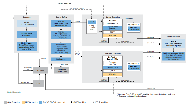
Figure 1.1 Block diagram of the startup process
1.1.1 POR
POR (Power On Reset) is a type of Destructive Reset in the microcontroller's reset categories. During this stage, the MCU formally starts up. If HSE (Hardware Security Engine) functionality is enabled, the MCU enters the HSE Boot phase; if HSE functionality is disabled, it directly enters the Boot to Safety phase.
1.1.2 HSE Boot
During power-up, the MCU performs a series of information security-related operations through HSE (if enabled), including encryption/decryption, certificate verification, and key parsing validation.
1.1.3 Boot to Safety
In this phase, the MCU first performs BIST (Built-In Self-Test) and obtains the BIST results through the mSel (Mode Selector) module.
Meanwhile, the mSel module is also used to invoke the power-on self-test functions of sCheck (Square Check), which typically includes ECC fault detection for RAM, FLASH, and bus-related components, clock self-test, FCCU channel self-test, and CRC self-test functionalities.
After the self-test completion, mSel determines whether to switch the MCU state mode based on the overall self-test results, with Normal mode and Degraded mode available as shown in the figure.
Normal Mode
In this mode, all application task functions are executed. Before entering this mode, the sBoot (Secure Boot) module is used to verify peripheral configurations. If the verification fails, the sReco (Software Recovery) module will be called to perform a functional reset. If the verification passes, the OS (if present) will be started to execute MCU's periodic tasks. As for the SAF package, it will perform specific periodic self-tests, such as SCST (Safety Core Self-Test) and sCheck (Square Check) periodic detection.
Degraded Mode
In this mode, certain functionality trimming operations are performed, which are entirely customized by users based on their actual requirements. Multiple degraded modes can be configured to handle different safety tasks in various fault scenarios.
1.1.4 ShutDown
The sCheck (Square Check) module is also designed with detection capabilities during power-down phase. Faults detected during self-test can be recovered in the next power-up cycle. After self-test completion, the results can be stored in NVM (Non-Volatile Memory) through the mSel (Mode Selector) module, allowing the results to be retrieved during the next power-up sequence.
2 Overview of SCST (Structural Core Self-Test)
The SCST (Structural Core Self-Test) component is used to detect various MCU core sub-modules (such as Load/Store units, Forwarding logic units, Floating-point units, etc.) during runtime to determine whether permanent core faults exist in the MCU core. Its diagnostic coverage typically reaches 90%. The integration is compiler-independent, and the detection code is written in assembly language. It can cover all required diagnostic test items without expensive fault simulation tools. The achievable safety level is ASIL B.
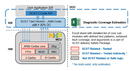
Figure 2.1 Overview of SCST library materials
3 INTEGRATION ISSUES GUIDANCE
This chapter demonstrates the SAF (Safety Application Framework) integration and troubleshooting process through a common issue encountered during SAF integration.
3.1.1 TCM (Tightly Coupled Memory) Fault
One of the most common issues encountered during SAF (Safety Application Framework) integration is TCM (Tightly Coupled Memory) related faults. For instance, after integration, during normal power-up, the FCCU (Fault Collection and Control Unit) module reports TCM faults causing continuous resets, while the code appears normal. How should we troubleshoot this situation?
First, let's look at the error information, as shown in the figure below:
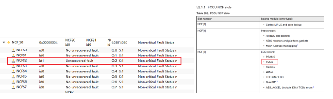
Figure 3.1 FCCU fault information
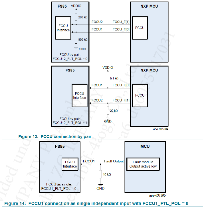
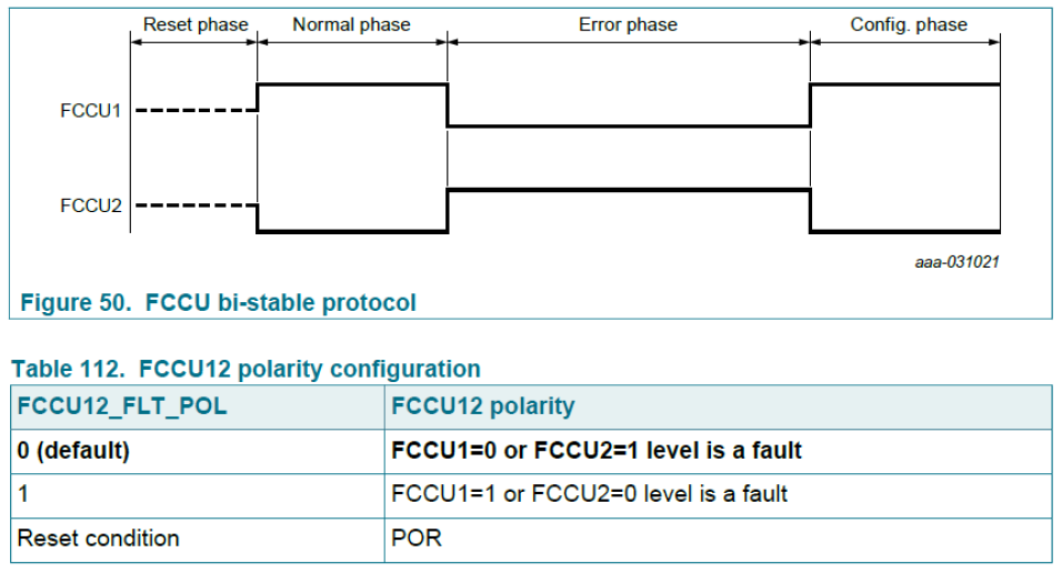
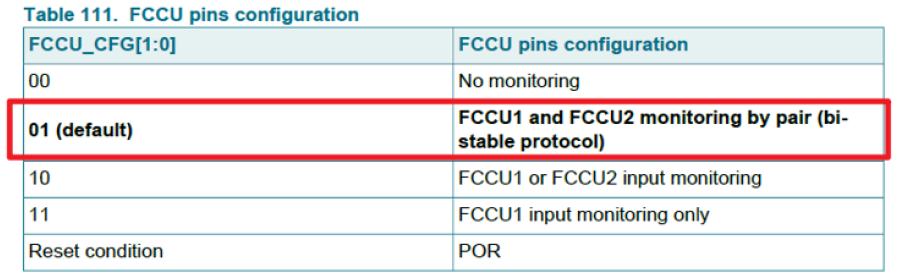
The FCCU (Fault Collection and Control Unit) is the fault collection unit of the S32K3 microcontroller, where most chip fault information can be read. Here, we observe that channel 2 status register is set to 1, and subsequent debugging reveals that a fault occurred when accessing the TCM (Tightly Coupled Memory) address. Referring to the chip manual, we can determine that the TCM component generated an ECC (Error Correction Code) fault, which was then reported to the FCCU.
3.1.2 ECC (Error Correction Code) Fault
Let's first briefly introduce the ECC mechanism. There are two failure modes for memory:
1. Illegal access, which is typically protected through memory management using MPU (Memory Protection Unit)
2. Memory corruption, which is generally diagnosed through ECC, and the ECC mechanism can be implemented in either software or hardware.
ECC (Error Checking and Correcting) is an error detection and correction algorithm. In digital circuits, the smallest data unit is called a "bit", which is also the smallest unit in memory, representing data through high and low level signals using "1" and "0". Wireless electromagnetic interference in space and circuit noise can cause bit flips ("0" changing to "1", "1" changing to "0") during data interaction between memory and CPU. Typical ECC algorithms can generally achieve Single-Bit Error Correction and Double-Bit Error Detection (SECDED).
Structure of ECC (Error Correction Code)
The number of required ECC bits is determined by the number of bits in the data segment. 8-bit data requires 5 ECC bits for verification, and for each doubling of data bits, only one additional ECC check bit is needed. For example, 32-bit data requires 7 ECC check bits.
ECC (Error Correction Code) Verification Process
The ECC encoding logic unit generates a 7-bit ECC check code during write operations. When data is read through the AHB (Advanced High-performance Bus) bus, the ECC decoding logic unit uses the same algorithm to calculate the check code for the read data, then compares it with the original check code to verify if they match.
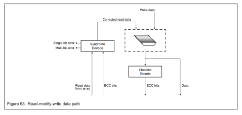
Figure 3.2 ECC Mechanism Verification Path of S32K3 Microcontroller

Figure 3.3 Conventional ECC Verification Mechanism
Therefore, the fault was triggered by accessing a TCM (Tightly Coupled Memory) address with an ECC (Error Correction Code) error, which resulted in the exception being generated.
3.1.3 TCM (Tightly Coupled Memory) Initialization)
Similar to SRAM, TCM (Tightly Coupled Memory) must also be initialized before use, otherwise ECC (Error Correction Code) faults may occur.
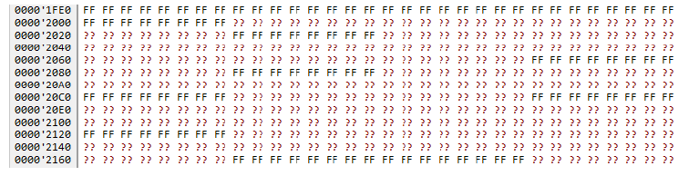
Figure 3.4 Debug View of ECC Fault Region
Below is a screenshot of the startup code from the demonstration project. We can observe that the startup code performs a zero-writing operation from __INT_DTCM_START to __INT_DTCM_END. As explained in section 3.1.2, the corresponding ECC check codes are refreshed during the write operation, which constitutes the initialization process of TCM.
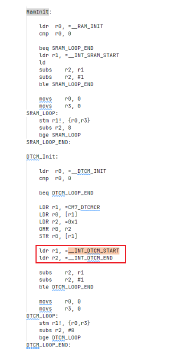
Figure 3.5 Screenshot of Startup Code
Finally, we can eliminate this fault by adjusting the linker script to extend the initialization range to cover the entire TCM (Tightly Coupled Memory) region.
3.1.4 Conclusion
During the integration of SAF (Safety Application Framework) safety package, similar ECC (Error Correction Code) issues are frequently encountered, which may involve SRAM, TCM, FLASH, or other components. The troubleshooting and resolution approaches are generally similar. By following the analysis steps mentioned above, most issues can be effectively resolved.
4 ZC Integration Services
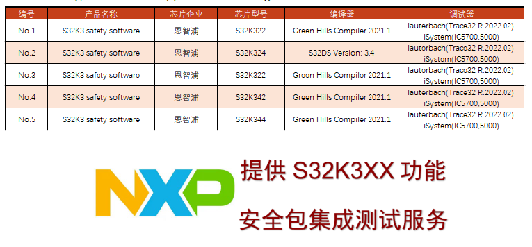
We provide integration testing services for NXP S32K3 series MCU's S32K3 safety software. Given that S32K3 Safety software requires dynamic configuration based on customer safety requirements to fully cover their application needs, we can perform configurations according to different project requirements, ultimately meeting the functional safety engineering needs of our customers.
Currently, our services support the following microcontrollers:
5 Technical Services
5.1 Functional Description
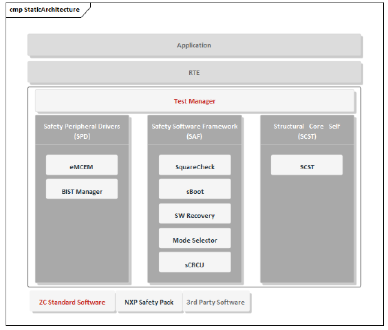
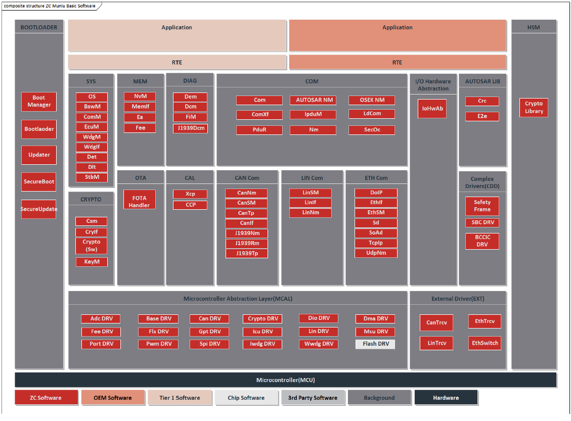
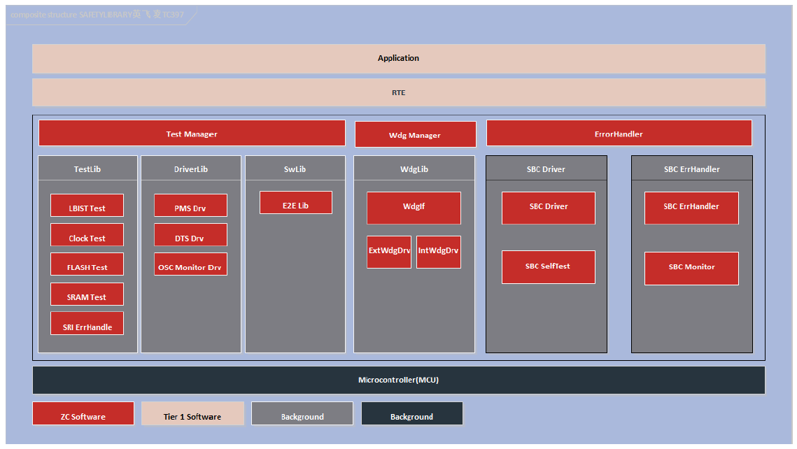
Figure 5.1 Safety Pack Software Architecture Diagram
During the integration of SAF & SCST safety package, a Test Manager module is added at the upper layer to call interface functions of each self-test module according to the startup sequence. At the user level integration, the entire SAF & SCST safety package functionality can be executed simply through the Test Manager interface, significantly improving integration efficiency.
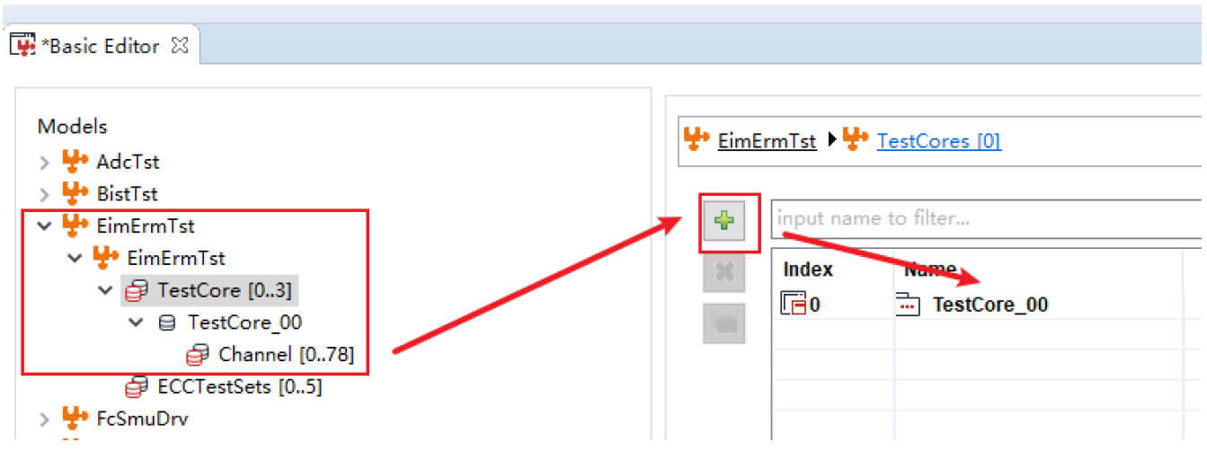
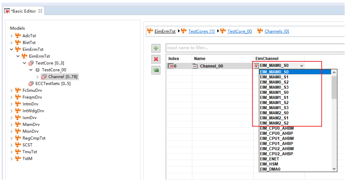
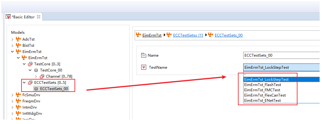
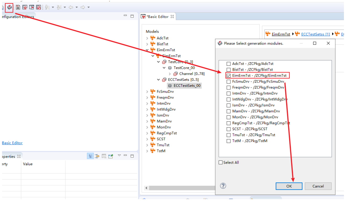
5.2 Introduction to ZC Test Manager Module
The Test Manager module is a core management and scheduling module added by ZC when integrating Safety Pack into actual projects. It is used to manage the Safety Pack test process and handle interfaces with the application layer. Additionally, it is paired with ZC's MuNiu configuration tool, which facilitates quick configuration of required detection modules.

Figure 5.2 MuNiu Configuration Tool Interface


 收起
收起