- 知从MCAL产品定制开发服务
- 知从VECTOR FBL产品工程服务
- 知从基于恩智浦S32K3系列芯片功能安全包可提供的服务
- 知从LIN一致性测试服务
- 知从科技基于英飞凌MOTIX™系列芯片 提供基础软件解决方案
- 知从基于恩智浦S32K3系列芯片功能安全包可提供的服务
- 知从E2E测试服务
- 从TRICORE平台到ARM CORTEX-R52/R52+的迁移指南
- 知从RTE测试服务
- 知从木牛恩智浦S32K1信息安全服务手册
- 知从功能安全工程服务
- 知从SafetyLibrary服务
- 知从VECTORMICROSAR产品工程服务
- 知从MCAL产品工程服务
- 知从ECU控制器开发功能服务
- 知从软件测试工程服务
- 知从HIL测试工程服务
- 知从TESTFACTORY工程服务
- 知从ADAS域控制器英飞凌MCU TC397
- 知从网关产品
- 便携式充电器
- 交流充电桩产品
1 概述
RTE是Autosar软件架构中,介于应用层和基础软件层之间,是Autosar虚拟功能总线VFB接口的实现,从而为应用软件ASW软件之间的通信提供基础设施服务,并促进对包括OS在内的基础软件BSW组件的访问。
RTE的测试包含COM,DIAG,NVM和SWC间的接口等测试,但目前从目前市场情况来看,RTE测试工具和方法稀少,原因是专门做RTE测试的市场规模小,多数供应商无愿开发RTE测试工具,导致测试工具的选择极其有限,且价格昂贵。而且纵观全行业,大部分和RTE测试相关的工具,都是基于配置工具,调试器,总线工具进行手动白盒测试,针对成千上万的RTE接口,测试量巨大且消耗大量人力资源。
针对以上描述的问题,知从科技可以提供一整套完整的RTE测试方案,解决客户的后顾之忧。
2 测试点
RTE测试主要针对于SWC和BSW之间 Read和Write接口,根据不同的接口制定不同的测试策略。包括但不限于:
Ø SWC和SWC之间接口
Ø SWC和COM之间接口
Ø SWC和DIAG之间接口
Ø SWC和NVM之间接口
Ø SWC和SPI之间接口
3 测试台架及环境-ADAS为例
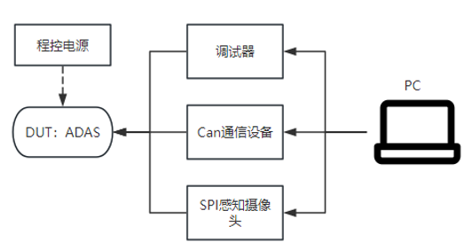
台架架构
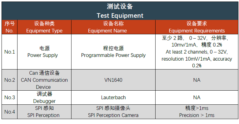
4 测试设备说明
4.1 硬件需求
4.2 软件需求
4.2.1 测试环境软件
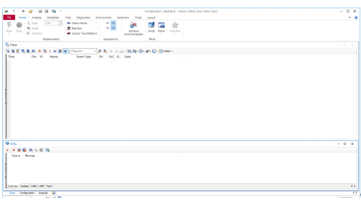
Vector CANoe 系列工具,版本Canoe12.0及以上
5 ADAS RTE测试步骤示例
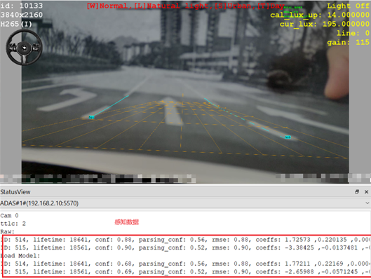
5.1 模拟真实场景,例如识别车道线,获取车道线数据
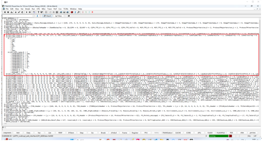
5.2 通过调试器观测接收数据

5.3 对比原始信号数据文件,判断SPI感知摄像头获取的数据与调试器数据是否一致。
5.4 测试SWC与SPI之间的接口是否正确。

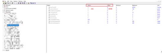
通过调试器读取RTE_Write中的结构体中的信号数据 ,计算出真实物理值。
通过信号值与结构体中变量对应关系,查找在Rte_Read接口下读取的结构体的数据,发现与原先计算的一致,则测试正确。
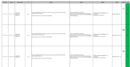
5.5测试报告
根据AUTOSAR_SWS_RTE规范和客户RTE接口的测试需求,并通过等价类,边界值等方法设计测试用例,完成测试报告,保证双向追溯性和一致性。