- 知从MCAL产品定制开发服务
- 知从VECTOR FBL产品工程服务
- 知从基于恩智浦S32K3系列芯片功能安全包可提供的服务
- 知从LIN一致性测试服务
- 知从科技基于英飞凌MOTIX™系列芯片 提供基础软件解决方案
- 知从基于恩智浦S32K3系列芯片功能安全包可提供的服务
- 知从E2E测试服务
- 从TRICORE平台到ARM CORTEX-R52/R52+的迁移指南
- 知从RTE测试服务
- 知从木牛恩智浦S32K1信息安全服务手册
- 知从嵌入式自动化测试服务
- 瑞萨RH850 G3MH/G3KH到ARM CORTEX-R52/R52+的迁移指南
- 知从ASPICE SWE04单元测试介绍
- 知从啸天信息安全算法工具(可直接下载试用)
- 知从功能安全工程服务
- 知从SafetyLibrary服务
- 知从VECTORMICROSAR产品工程服务
- 知从MCAL产品工程服务
- 知从ECU控制器开发功能服务
- 知从软件测试工程服务
- 知从HIL测试工程服务
- 知从TESTFACTORY工程服务
- 知从ADAS域控制器英飞凌MCU TC397
- 知从网关产品
- 便携式充电器
- 交流充电桩产品
1 Test Factory介绍
汽车行业发展进入高速发展期,尤其是智能驾驶研发,其中软件代码量急剧上升,对汽车功能和性能的要求不断升高,研发周期不断缩短,对测试任务提出了更高要求。为了最大可能重复利用可重复利用的资源,以及降低成本,测试工厂可以为客户提供系统需求验证,通讯诊断验证,功能验证,性能测试,功能安全,信息安全评估以及测试技术咨询,测试仿真环境设计和工具使用。
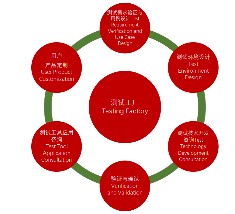
图 1‑1 测试工厂服务
2 TEST Factory 服务保证
2.1 测试需求验证与用例设计
收集客户产品需求及系统环境需求,软件需求,硬件需求,并进行详细分析验证,按需求工程理论,测试策略,测试技术,编辑和管理测试需求说明文档。
服务范围:
Ø 企业标准需求分析,如:总线设计标准,网络设计标准,诊断服务标准等,以企业标准为高优先级;
Ø 客户需求,系统设计需求验证,如:具体产品的系统需求,BCM,BMS,VCU等
Ø 软件功能分析,详细的软件逻辑功能模块;
Ø 功能安全需求分析,如:按功能安全ISO26262进行测试设计;
Ø 信息安全分析,依据ISO 21434,SAEJ3061-2016开展分析验证。
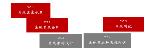
图 2‑1 系统工程流程
2.2 ECU测试
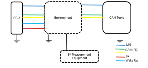
图 2‑2 ECU 测试环境示意图
Ø 标准测试
依据企业标准提供测试服务:
a) CAN(FD)总线一致性测试,涵盖了物理层,数据链路层,总线容错,采样点等;
b) LIN总线一致性测试, 涵盖了物理层,数据链路层,节点配置/网络管理;
c) 车载以太网测试,物理层测试,分发送端测试、接收端测试、线缆连接器合规性测试;
d) CAN网络管理测试,涵盖OSEK 网络管理,AutoSAR网络管理,主从节点网络管理;
e) 诊断服务测试,涵盖CAN诊断服务,LIN诊断服务;
f) Boot loader测试。
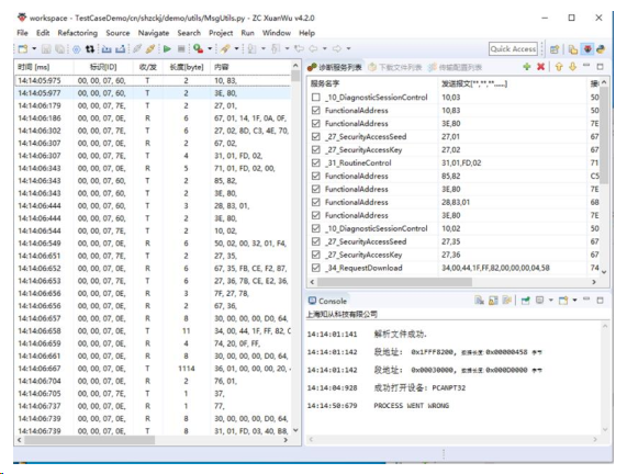
图 2‑3 玄武诊断服务
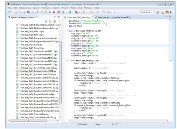
图 2‑4 玄武诊断服务测试用例
Ø 功能性测试
针对具体电子控制器功能测试,如:电池管理单元,车身控制单元,整车控制单元,车门控制单元,混合动力控制器等。
验证ECU的功能和技术要求的正确性,完整性。
a) ECU模型测试;
b) ECU系统测试;
c) ECU软件子功能测试;
d) ECU电源管理验证;
e) ECU功能安全需求测试;
f) ECU信息安全需求测试;
g) ECU验收测试<或发布测试>;
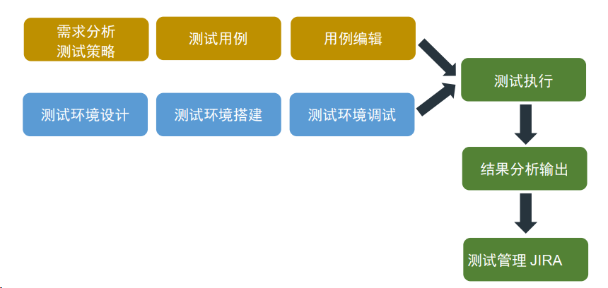
图 2‑5 测试开发基本流程
针对安全性机制,以及覆盖率还需进行更多验证,
Ø 故障注入验证,诊断应用测试,基于功能安全目标测试等;
Ø 经验验证;
Ø 与模型比较验证;
Ø 鲁棒性验证,压力测试,耐久测试,负载测试,可靠性测试;
2.3 整车测试
Ø 整车节点网络通讯验证, 可分AutoSAR 网络管理,OSEK网路管理,主从式网络管理;
Ø 整车功能仿真验证;
Ø 实车功能验证;
Ø 实车故障分析;
Ø 整车标定测量;
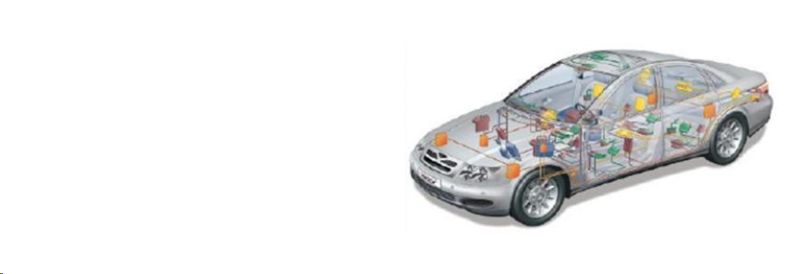
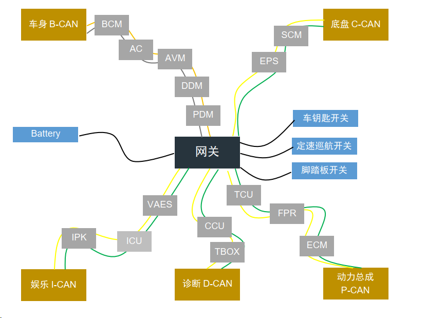
图 2‑6 整车网络拓扑示意图
2.4 测试环境设计
Ø HIL 测试系统方案设计
需求评估;
硬件环境搭建,实时仿真系统选择,
Ø VT System
Ø DSPACE
Ø NI
测试软件设计,可划分为:测试应用层,测试功能层,抽象层,驱动层。

图 2‑7 测试软件架构示意图
参考应用工具:Vector CANoe + vTESTstudio + VT System.
Ø 整车网络仿真环境设计
Design of vehicle network simulation environment
依据客户数据库Data Base文件的输入,进行网络通讯环境的仿真设计,如:
Ø 符合OSEK Nm通讯环境,基于OSEKNM01.dll;
Ø 符合AutoSAR Nm通讯环境,基于AsrNM33.dll或AsrNM30.dll。
注:建议定制仿真软件包,玄武工具包。
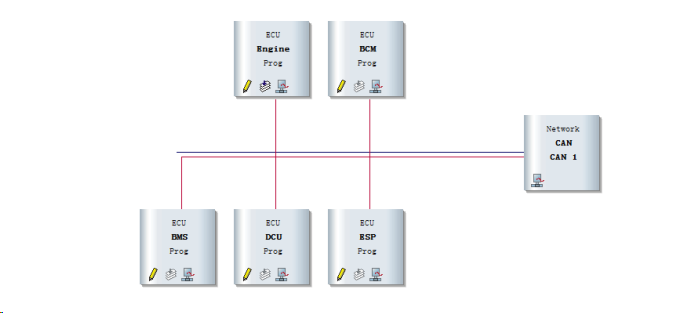
图 2‑8 网络仿真节点示意图
参考应用工具:Vector CANoe软件 + Vector 通讯硬件。
Ø 手动测试负载仿真环境设计
电源管理控制,总线(CAN, LIN,Ethernet)通讯环境,负载仿真,故障注入控制;
参考应用工具:非标定制 - 总线及IO仿真箱。
Ø HIL系统与待测ECU闭环调试
结合被测对象功能和系统环境,调试手动环境,并进行自动化测试用例开发。
2.5 测试技术开发及工具应用咨询
Ø 测试理论
涵盖测试开发基本过程,测试级别,测试类型,测试策略,测试技术,测试管理,测试工具支持等。
Ø 测试技术咨询
基本测试技术方法应用,等价类划分,边界值分析,决策表分析,状态转换测试,用例测试,组合测试,基于经验的测试技术,故障注入测试,以及基于检查表,基于质量特征验证等。
Ø 测试工具技术咨询及应用
Ø 总线工具,CANoe
Ø 诊断测试工具
Ø 测量标定
Ø HIL 系统
Ø HIL环境搭建技术咨询
以VT System环境搭建为例:
Ø 被测对象功能需求评估,负载资源评估;
Ø VT 资源板卡选型与确定;
Ø 系统平台化设计;
Ø HIL环境测试软件平台设计 ;
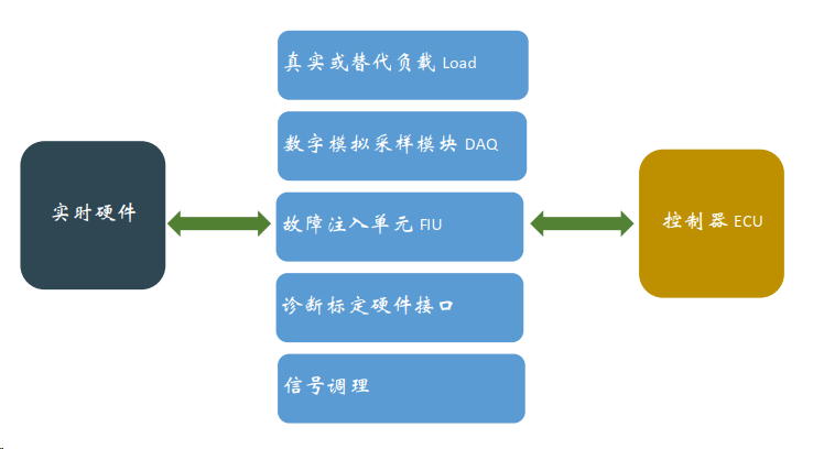
图 2‑9 硬件在环系统示意图
2.6 用户产品定制
Ø 桌面手动测试箱
Ø HIL自动化测试柜
Ø CAN(FD)一致性测试柜
Ø LIN一致性测试柜
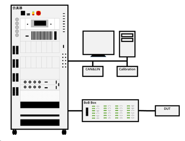
图 2‑10 标准化HIL自动化测试系统

点击下载产品手册